Method to Increase Aircraft Maximum Landing Weight Limitation

a maximum landing weight and aircraft technology, applied in vehicle position/course/altitude control, process and machine control, instruments, etc., can solve the problems of limiting the planned load, overweight landing event, severe storm passing through the area,

Inactive Publication Date: 2012-09-13
NANCE C KIRK
View PDF44 Cites 5 Cited by
  • Summary
  • Abstract
  • Description
  • Claims
  • Application Information

AI Technical Summary

Benefits of technology

[0043]There is provided a method of operating an aircraft, the aircraft having a first maximum landing weight based upon a first assumed maximum descent velocity. Vertical velocities are obtained of the aircraft at initial contact of the aircraft with the ground during landing events. Based upon the obtained vertical velocities of the aircraft at initial contact with the ground, operating the aircraft at or below a second assumed maximum descent velocity while measuring and recording the vertical velocities of the aircraft at initial contact of the aircraft with the ground during subsequent landing events, the second assumed maximum descent velocity being less than the first assumed maximum descent velocity. Operating the aircraft at a second maximum landing weight based upon the second assumed maximum descent velocity.

Problems solved by technology

Aircraft have limitations regarding the maximum allowable force the aircraft landing gear and other supporting structures of the aircraft can safely absorb when the aircraft lands.
With this high volume of daily flights, situations such as medical emergencies or minor equipment malfunctions often arise where an aircraft has left the departure airport, and the pilot discovers the need to immediately return and land, without the time or opportunity to burn-off the planned in-route fuel.
This causes an overweight landing event.
Weather forecasts had the possibility of severe storms passing through the area of the destination airport.
Because an overweight landing causes the aircraft to be removed from service for inspection, which severely disrupts the airline's planned operations, airlines work to avoid such events.
As a result, aircraft operators will restrict the planned load, and an aircraft may take-off with un-used capacity.
The weight carrying ability of the aircraft is thus limited, not by the maximum take-off weight limitation, but by the MLW limitation.
Though current regulations for aircraft design criteria acknowledge aircraft structural integrity to allow the aircraft to land at a weight greater than the originally certified MLW for that aircraft, with there being no active and operational system to accurately measure the VVG of those higher landing weight aircraft, there have been no justifications for the aviation Regulatory Authorities to allow for planned or scheduled landing events at the higher weights.
When aircraft leave a manufacture's assembly facility, there are no assurances that all subsequent landing events will be soft or smooth.

Method used


Image

  • Method to Increase Aircraft Maximum Landing Weight Limitation
  • Method to Increase Aircraft Maximum Landing Weight Limitation
  • Method to Increase Aircraft Maximum Landing Weight Limitation

Examples


embodiment

Preferred Embodiment

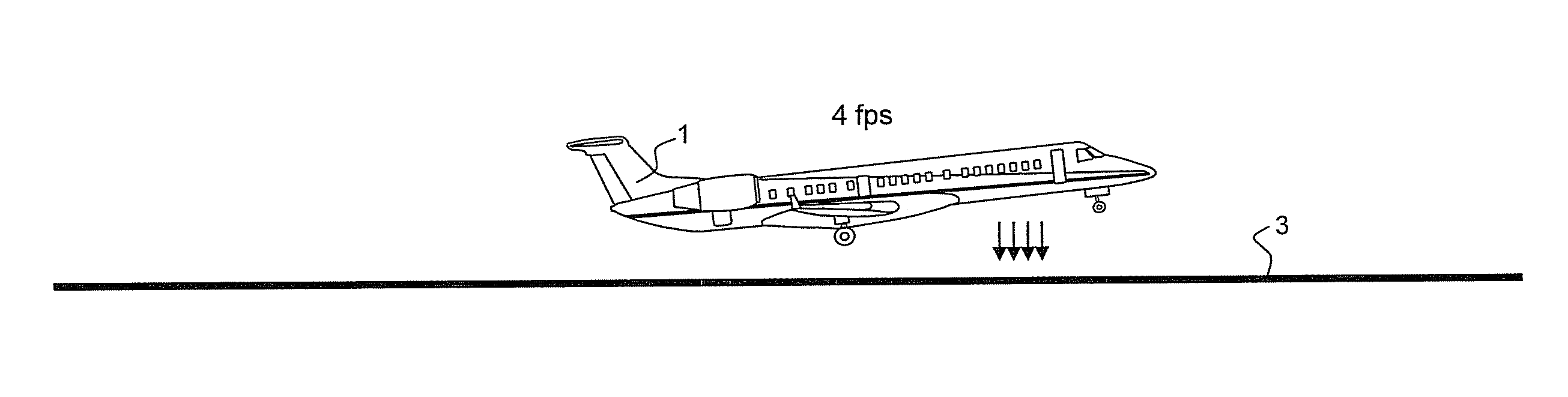
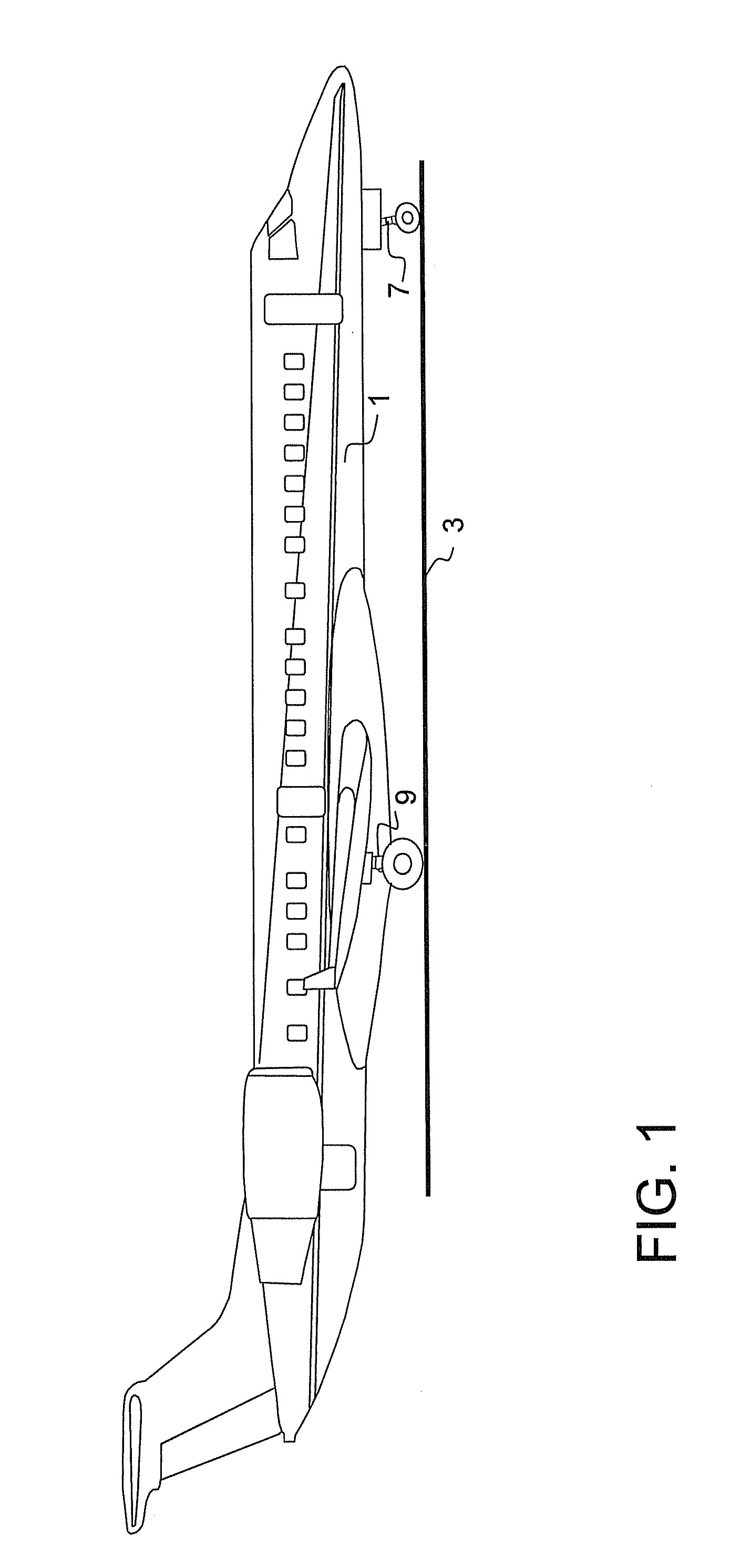
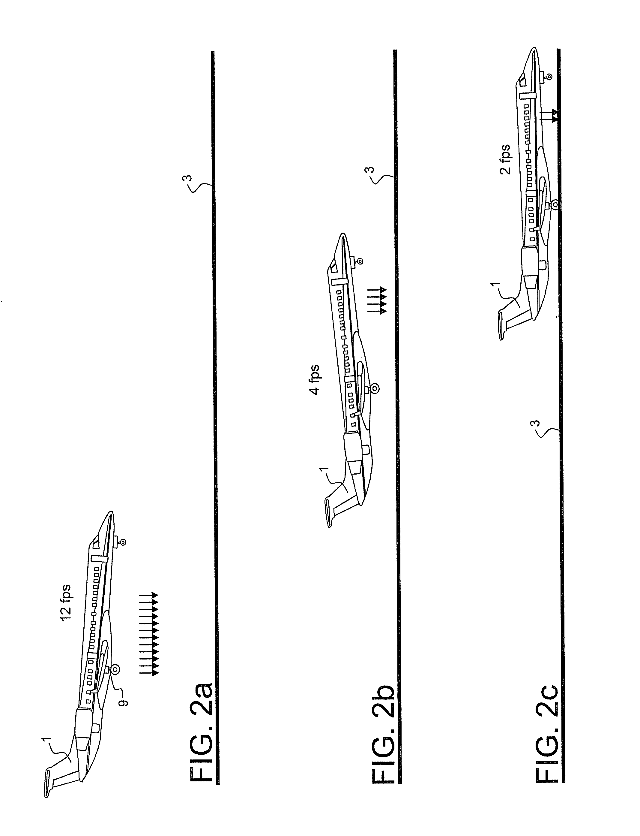
[0072]The present invention creates a “justification basis” for a Regulatory Authority to allow for a reduction in the current regulatory assumptions of aircraft sink-speed or VVG, by use of measured VVG, to further allow an increase in the MLW limitation of the aircraft. The present invention incorporates devices which measure and determine aircraft sink-speed through various methods including the compression rate experienced by each landing gear strut on initial contact with the ground. The strut is monitored for compression so as to confirm that the aircraft has come into contact with the ground and also to determine the rate of strut compression and the aircraft vertical descent velocity or VVG.

[0073]The present invention detects initial and continued compression of the landing gear strut by rapidly monitoring angle changes in landing gear torque-link, and / or internal strut pressure, prior to initial contact with the ground; as well as throughout the remainde...


PUM


Abstract

A method of establishing a justification basis to Aircraft Regulatory Authorities, to allow for a reduction in aircraft sink-speed assumptions. To further allow the aircraft to operate an increased maximum landing weight limitation. A system for use in measuring aircraft vertical velocity at initial contact with the ground, experienced while aircraft are executing either normal or hard landing events. Pressure sensors are attached to the working pressure within the landing gear strut, so to monitor in-flight landing gear strut pre-charge pressure, until such time as the pre-charge pressure suddenly increases, to detect the aircraft has come into initial contact with the ground. Rotation sensors are attached to the hinged elements of the landing gear strut, so to monitor in-flight landing gear strut extension, until such time as the strut extension suddenly decreases, to detect the aircraft has come into initial contact with the ground.

Description

[0001]This application claims the benefit of U.S. provisional patent application Ser. No. 12 / 469,976, filed May 21, 2009.BACKGROUND OF THE INVENTION[0002]An aircraft is typically supported by plural pressurized landing gear struts. Designs of landing gear incorporate moving components which absorb the impact force of landing. Moving components of an aircraft landing gear shock absorber are commonly vertical telescopic elements. The telescopic shock absorber of landing gear comprise internal fluids, both hydraulic fluid and compressed nitrogen gas, and function to absorb the vertical descent forces generated when the aircraft lands.[0003]The amount of force generated when an aircraft lands is a function of the aircraft weight at landing, and the vertical velocity at which that aircraft landing weight comes into initial contact with the ground. Aircraft have limitations regarding the maximum allowable force the aircraft landing gear and other supporting structures of the aircraft can ...

Claims


Application Information

Patent Timeline
Patent Type & Authority Applications(United States)
IPC IPC(8): G05D1/06B64C25/02
CPCB64C25/00G05D1/0083G05D1/0066B64D2045/008
Inventor NANCE, C. KIRK
Owner NANCE C KIRK
Why Eureka
Try Eureka