Oil separator and refrigerating cycle apparatus using the same

a technology of oil separator and refrigerating cycle, which is applied in the direction of refrigerating machines, lighting and heating apparatus, refrigeration and liquidation, etc. it can solve the problems of increasing manufacturing costs, affecting the flow of refrigerant, and floats may lose buoyancy, so as to reduce manufacturing costs, reduce manufacturing costs, and eliminate pressure differences

Active Publication Date: 2012-09-20
PANASONIC HEALTHCARE HLDG CO LTD
View PDF6 Cites 7 Cited by
  • Summary
  • Abstract
  • Description
  • Claims
  • Application Information

AI Technical Summary

Benefits of technology

[0016]This configuration eliminates a pressure difference between the interior and the exterior of the float. Therefore a problem of breakage of a float due to a high pressure in the tank and a pressure change can be solved with a simple configuration even for a float with a low strength. Accordingly, burning of a compressor or cooling error of a refrigerating cycle apparatus as in the aforementioned sixth aspect of the present application can be effectively prevented while remarkably reducing the manufacturing cost. In case where oil enters into the float from the other end of the equalizing means, the oil flows out from the tank through the equalizing means when the pressure in the tank decreases, and so this configuration is free from the problem about buoyancy.
[0017]In this case, the other end of the equalizing means opening downward as in the second aspect of the present application can effectively prevent or suppress the problem that oil separated from a refrigerant flowing into the tank and typically dropping from the filter located above enters from the other end of the equalizing means.
[0018]The other end of the equalizing means opening obliquely upward as in the third aspect of the present application allows oil dropping from the above to tend to flow downward along the outer face of the equalizing means. Therefore this configuration also can effectively prevent or suppress entering of oil from the other end to the equalizing means.
[0019]The equalizing means disposed along an outer face of the float as in the fourth aspect of the present application can eliminate the necessity of providing equalizing means in the float, thus improving productivity more.
[0020]As in the fifth aspect of the present application, the float includes first and second float members each having a flange at an end face, the float members being welded at the flanges, and the equalizing means includes an equalizing path provided in the flanges. This configuration can realize equalizing means without using a pipe or the like, thus reducing the number of components and leading to the improvement of productivity.

Problems solved by technology

The oil discharged to the refrigerant cycle hinders circulation of the refrigerant at the pressure reducing unit and the evaporator, and causes problems such as burning due to depletion of the oil in the compressor.
The float is typically configured by welding two separated hemispheres (having a hollow inside) made of metal such as iron or stainless steel at their flanges, and the welding of high quality is required as well, thus increasing the manufacturing cost.
Additionally, due to metal fatigue inevitably generated in the float because of the pressure change with time, the float may lose the buoyancy by oil entering into the float through a broken portion.
In that case, the float cannot detect up / down movement of the oil level and so the oil-returning function is unfortunately disabled.

Method used


Image

  • Oil separator and refrigerating cycle apparatus using the same
  • Oil separator and refrigerating cycle apparatus using the same
  • Oil separator and refrigerating cycle apparatus using the same

Examples


Embodiment Construction

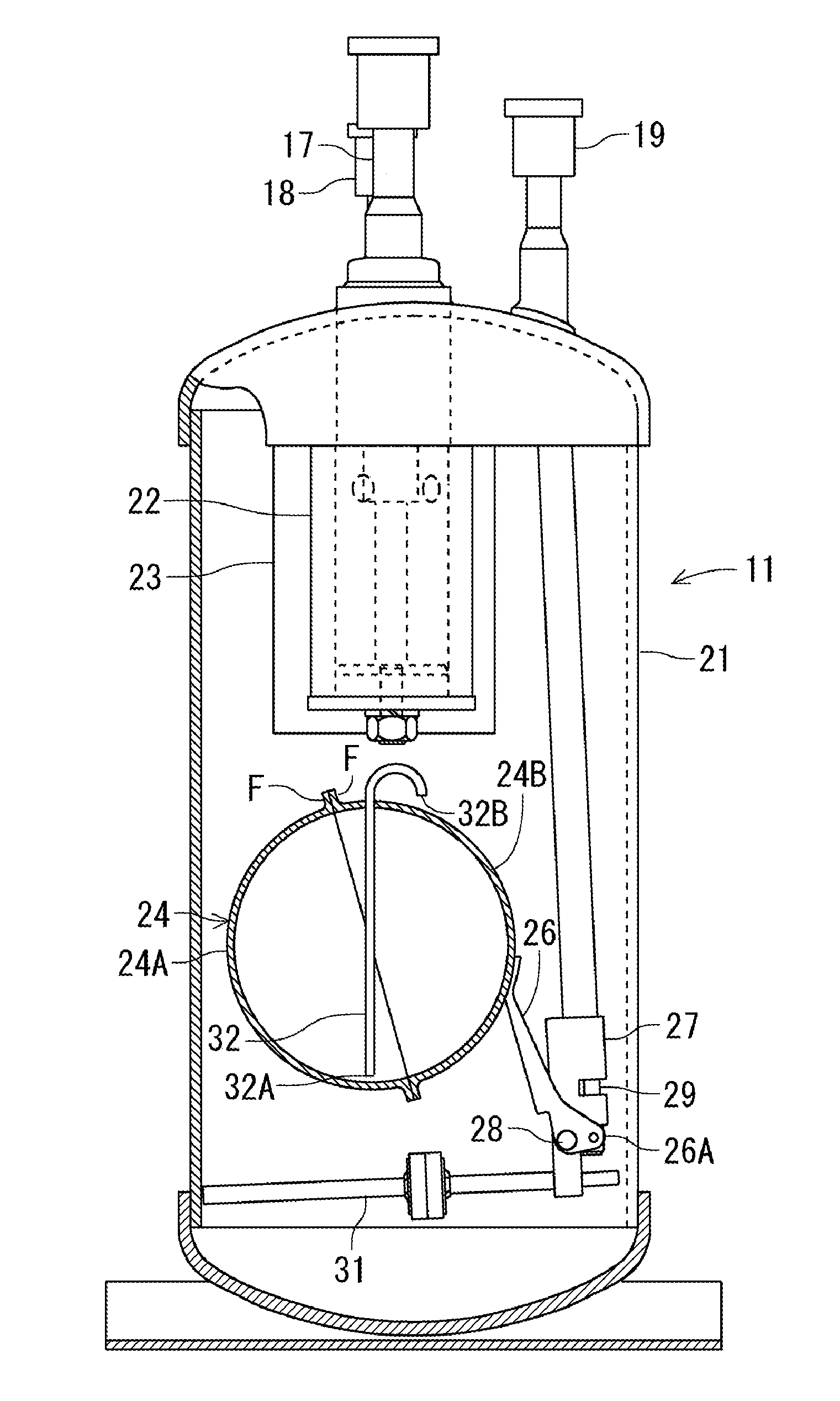
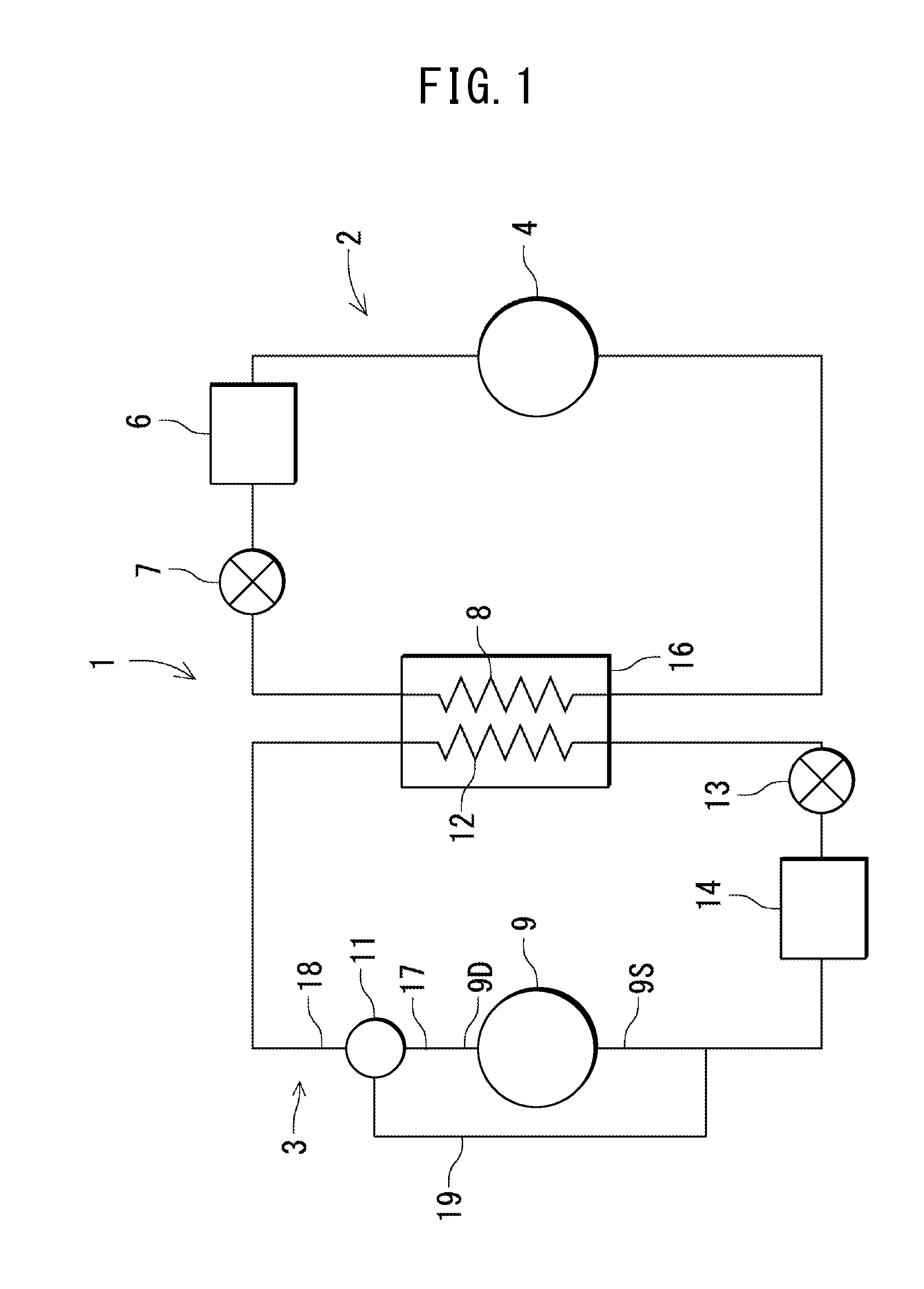
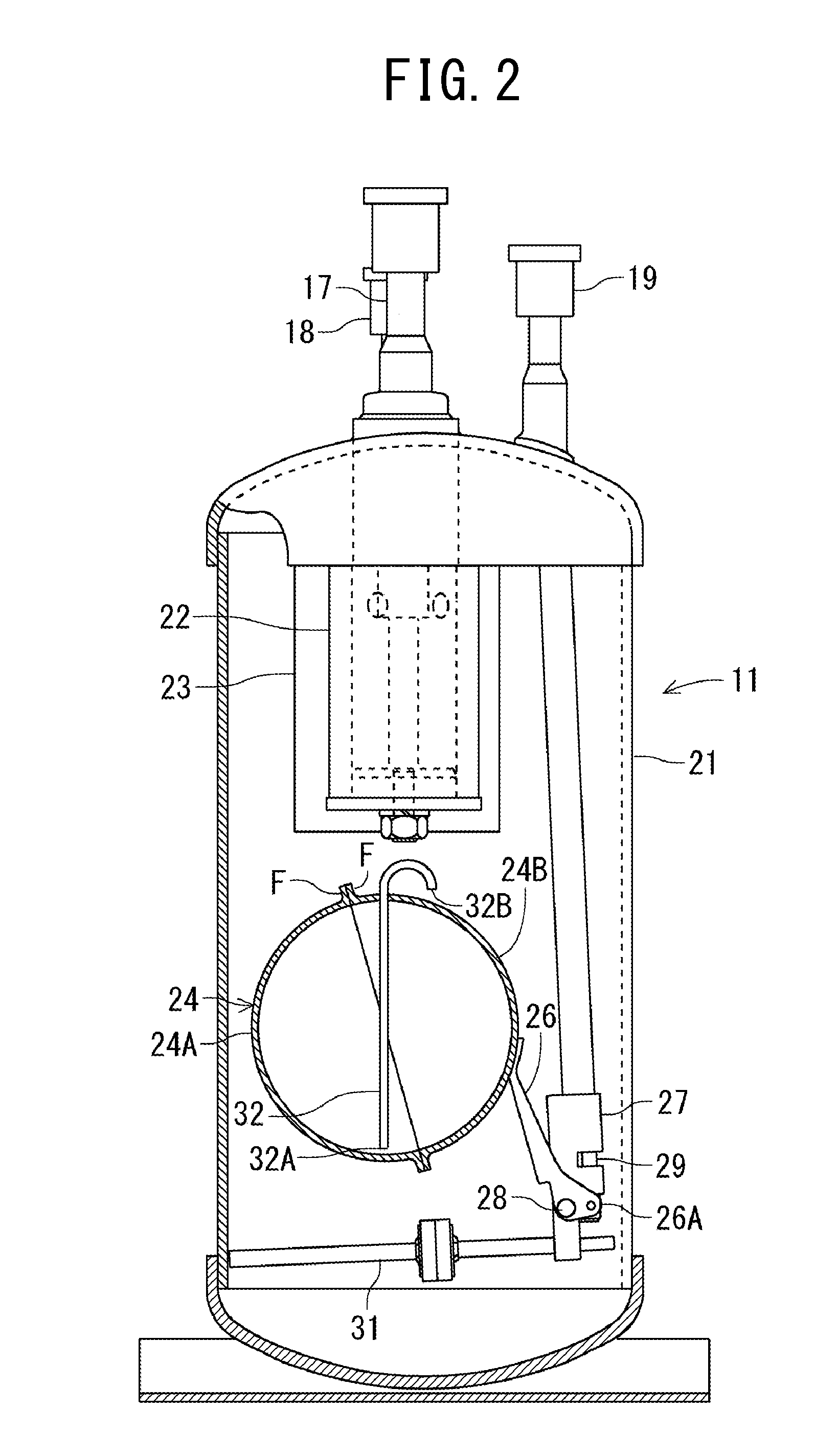
[0029]The following describes embodiments of the present invention in detail, with reference to the drawings. A refrigerant circuit illustrated in FIG. 1 is to cool the chamber (not illustrated) of a deep freezer 1 that is an embodiment of a refrigerating cycle apparatus of the present invention to ultracold temperatures from −80° C. to −150° C., and the refrigerant circuit includes a high-temperature side refrigerant circuit 2 and a low-temperature side refrigerant circuit 3 cascaded to the high-temperature side refrigerant circuit 2.

[0030]The high-temperature side refrigerant circuit 2 includes: a compressor 4; a condenser 6 as a radiator; a capillary tube (or an expansion valve) 7 as a pressure reducing unit and an evaporator 8 that are connected sequentially in a loop via pipes. The low-temperature side refrigerant circuit 3 includes: a compressor 9; an oil separator 11 according to the present invention; a condenser 12 as a radiator; a capillary tube (or an expansion valve) 13 ...


PUM


Abstract

An oil separator capable of preventing breakage in a float with an extremely simple configuration is provided. An oil separator is to separate oil in a refrigerant that is discharged from a compressor and return the oil to the compressor. The oil separator includes: a tank, into which a refrigerant discharged from the compressor flows; a float having a hollow therein that is held vertically movably in the tank, the float moving up and down with a change of an oil level in the tank; and a needle valve to return oil in the tank to the compressor in accordance with up / down movement of the float. The float includes an equalizing tube having a lower end that opens at a bottom part in the float and an upper end that opens outside of the float and above the oil level in the tank.

Description

TECHNICAL FIELD OF THE INVENTION[0001]The present invention relates to oil separators to return oil in a refrigerant that is discharged from a compressor in a refrigerating cycle apparatus such as a deep freezer and relates to refrigerating cycle apparatuses using the same.BACKGROUND OF THE INVENTION[0002]Conventionally deep freezers used for laboratories or the like are provided with a refrigerating cycle including a refrigerant circuit where a compressor, a condenser (radiator), a pressure reducing unit, an evaporator and the like are connected sequentially in a loop. This refrigerating cycle is filled with a refrigerant as well as a predetermined amount of oil to lubricate a sliding portion of the compressor. A part of this oil is discharged to the refrigerating cycle from the compressor together with the refrigerant.[0003]The oil discharged to the refrigerant cycle hinders circulation of the refrigerant at the pressure reducing unit and the evaporator, and causes problems such a...

Claims


Application Information

Patent Timeline
Patent Type & Authority Applications(United States)
IPC IPC(8): F25B43/02
CPCF25B43/02F25B2700/03F25B2500/06
Inventor TADANO, RIKIOSATOU, HIROYUKIKOBAYASHI, SUSUMUYAMAWAKI, HIROSHI
Owner PANASONIC HEALTHCARE HLDG CO LTD
Why Eureka
Try Eureka