Igniter with a locked consolidated powder charge

a powder charge and ignition charge technology, applied in the direction of electric fuzes, weapons, ammunition fuzes, etc., can solve the problems of sleeve not preventing the rotation of ignition charge, bridge wire failure, cost of additional components,

Inactive Publication Date: 2012-09-20
SPECIAL DEVICES
View PDF4 Cites 7 Cited by
  • Summary
  • Abstract
  • Description
  • Claims
  • Application Information

AI Technical Summary

Benefits of technology

[0008]According to a fourth aspect of the invention, this is achieved by an igniter comprising: a defined space filled with at least an ignition charge; a bridge wire that is at least partially in heat transmitting contact with the ignition charge; and a means for locking the ignition charge into place with respect to the bridge wire such that any substantial relative motion between the ignition charge and the bridge wire is prevented.

Problems solved by technology

During exposure to the environments such as thermal shock and cycling, the ignition plus output charge could become loose in the output can and stress the bridge wire during mechanical shock or vibration that could lead to bridge wire failure.
Such failures are due to both loose powder slug rattling as well as the powder slug rotating inside the output can applying both tensile and torsional loads on the bridge wire under severe environments.
However, in many instances the charge sleeve does not prevent the ignition charge from rotating due to environments which in turn could stress the bridge wire to a point of failure or degradation.
The disadvantage of using a charge sleeve is the cost of additional components, additional assembly steps and additional space required for this type of construction.

Method used


Image

  • Igniter with a locked consolidated powder charge
  • Igniter with a locked consolidated powder charge
  • Igniter with a locked consolidated powder charge

Examples


first embodiment

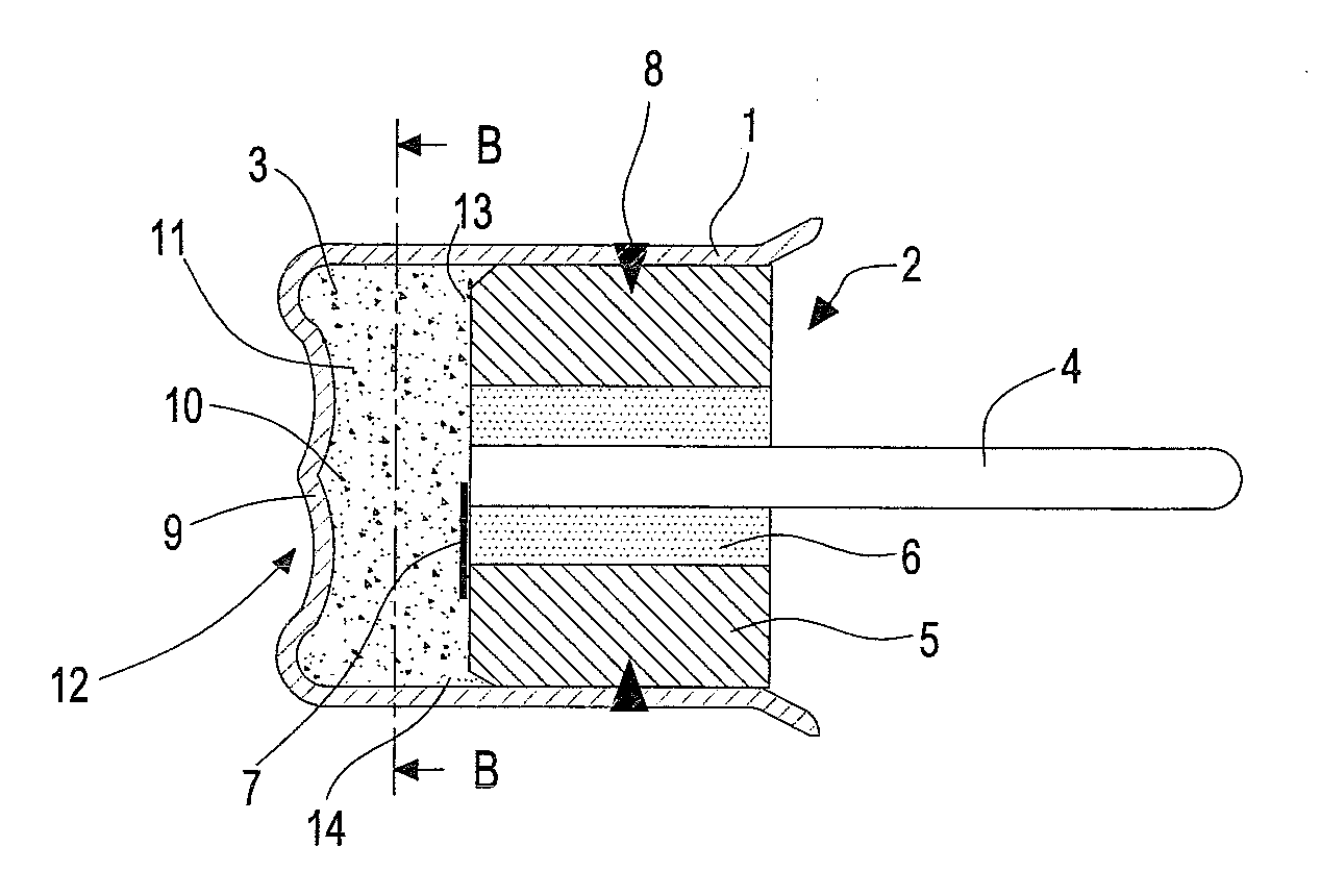
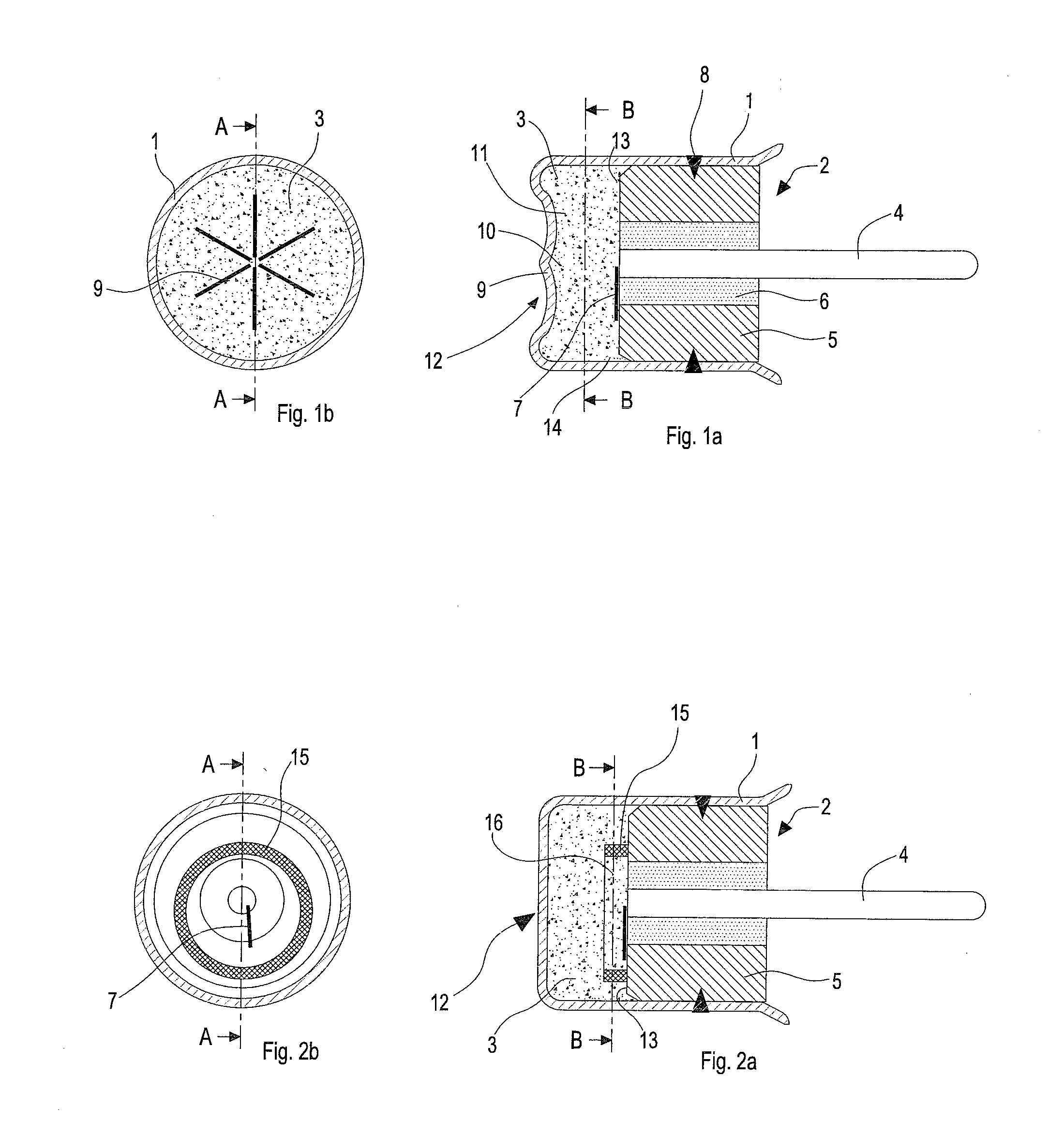
[0032]FIG. 1a shows a sectional view denoted A-A in FIG. 1b of a first embodiment comprising an output can having a consolidated ignition and output powder charge.

[0033]FIG. 1b shows a sectional view denoted B-B in FIG. 1a of the first embodiment shown in FIG. 1a.

second embodiment

[0034]FIG. 2a shows a sectional view denoted A-A in FIG. 2b of a second embodiment comprising an output can having a consolidated ignition and output powder charge.

[0035]FIG. 2b shows a sectional view denoted B-B in FIG. 2a of the second embodiment shown in FIG. 2a.

third embodiment

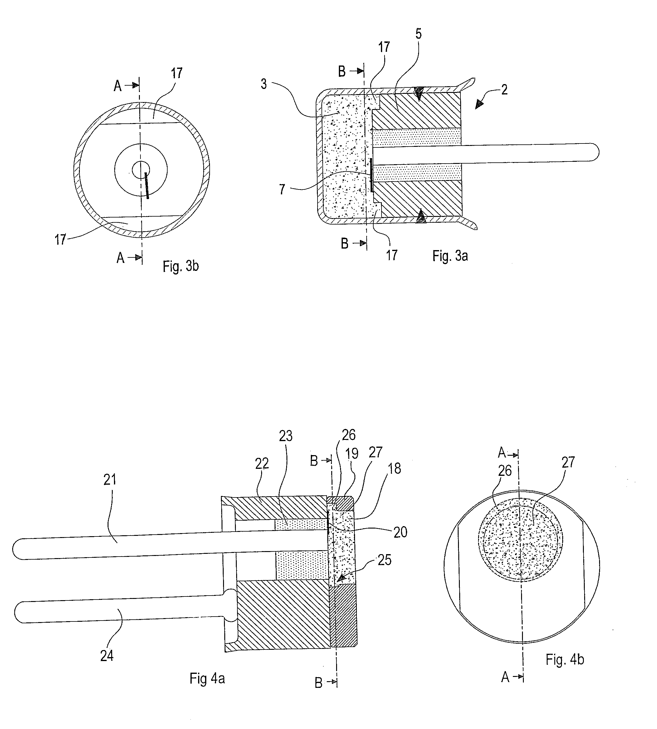
[0036]FIG. 3a shows a sectional view denoted A-A in FIG. 3b of a third embodiment comprising an output can having a consolidated ignition and output powder charge.

[0037]FIG. 3b shows a sectional view denoted B-B in FIG. 3a of the third embodiment shown in FIG. 3a.

[0038]FIG. 4a shows a sectional view denoted A-A in FIG. 4b of a first embodiment comprising a charge sleeve having a consolidated ignition powder charge.

[0039]FIG. 4b shows a sectional view denoted B-B in FIG. 4a of the first embodiment shown in FIG. 4a.

[0040]FIG. 5a shows a sectional view denoted A-A in FIG. 5b of a second embodiment comprising a charge sleeve having a consolidated ignition powder charge.

[0041]FIG. 5b shows a sectional view denoted B-B in FIG. 5a of the second embodiment shown in FIG. 5a.

[0042]FIG. 6a shows a sectional view denoted A-A in FIG. 6b of a third embodiment comprising a charge sleeve having a consolidated ignition powder charge.

[0043]FIG. 6b shows a sectional view denoted B-B in FIG. 6a of t...


PUM


Abstract

An igniter is described comprising a defined space filled with at least an ignition charge; a bridge wire that is at least partially in heat transmitting contact with the ignition charge; and a means for locking the ignition charge into place with respect to the bridge wire such that any substantial relative motion between the ignition charge and the bridge wire is prevented. This prevents movement of an ignition charge within an igniter, particularly movement of an ignition charge relative to a bridge wire in order to protect the bridge wire from failure such as detaching or breaking.

Description

FIELD OF THE INVENTION[0001]The present invention relates to initiators, primers and micro gas generators (MGG) used for automotive, military & industrial applications.BACKGROUND OF THE INVENTION[0002]In some initiators, primers and MGG designs—which should be understood as collectively covered by the more generic term “igniters” used in the following, the bridge wire is not protected by any ignition charge holder and the ignition charge and output charges are always in intimate contact with each other such that a good heat transfer from the bridge wire into the output charge is guaranteed. The output powder and ignition are consolidated together using a bridged header pressing into an output can. The output can, the consolidated powder charge, and the bridged header have typically been concentric to each other. During exposure to the environments such as thermal shock and cycling, the ignition plus output charge could become loose in the output can and stress the bridge wire during...

Claims


Application Information

Patent Timeline
Patent Type & Authority Applications(United States)
IPC IPC(8): F42D1/05
CPCF42B3/195F42B3/125F42B3/124
Inventor TIRMIZI, ABRAR A.AVETISIAN, VAHANVAWTER, GLORIA
Owner SPECIAL DEVICES
Why Eureka
Try Eureka