Nozzle Device for Pump

a technology for nozzles and pumps, applied in the direction of valve housings, positive displacement liquid engines, couplings, etc., can solve the problems of high manufacturing cost, inconvenient operation, and inability to detach the connector and the nozzle, so as to facilitate the change of operating modes and reduce costs. , the structure is simpl

Inactive Publication Date: 2012-09-20
WU NA
View PDF10 Cites 17 Cited by
  • Summary
  • Abstract
  • Description
  • Claims
  • Application Information

AI Technical Summary

Benefits of technology

[0008]An advantage of the nozzle device according to the present invention is that a cross section of a limiting portion of the core set is substantially the same with that of a chamber of the body and users can easily change the operating mode by pivoting the controller.
[0009]Another advantage of the nozzle device according to the present invention is that the core set is moved along the chamber and there has no gap between the chamber and the core set such that the structure is simple and the cost is decreased, furthermore, the size of t

Problems solved by technology

The conventional inflating device needs a large size shell for installation of the two connectors such that the shell might interfere with respect to a spoke while operation.
The structure thereof,

Method used


Image

  • Nozzle Device for Pump
  • Nozzle Device for Pump
  • Nozzle Device for Pump

Examples


first embodiment

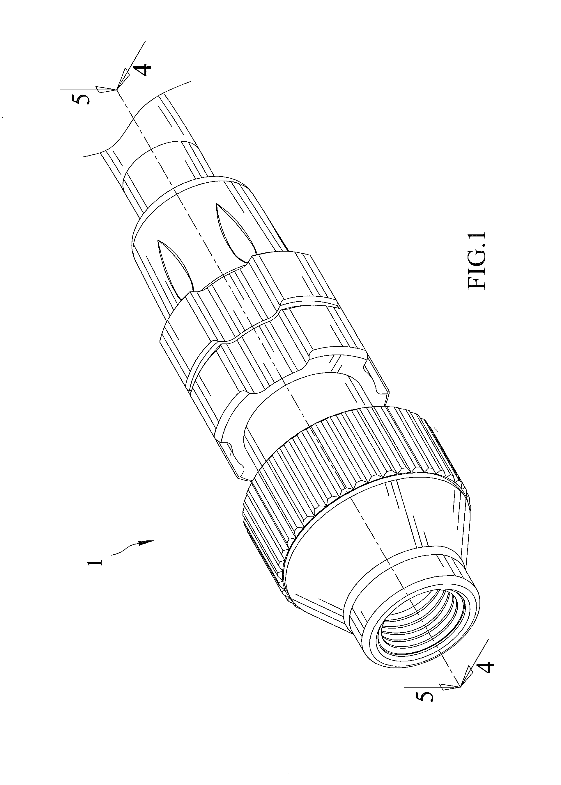
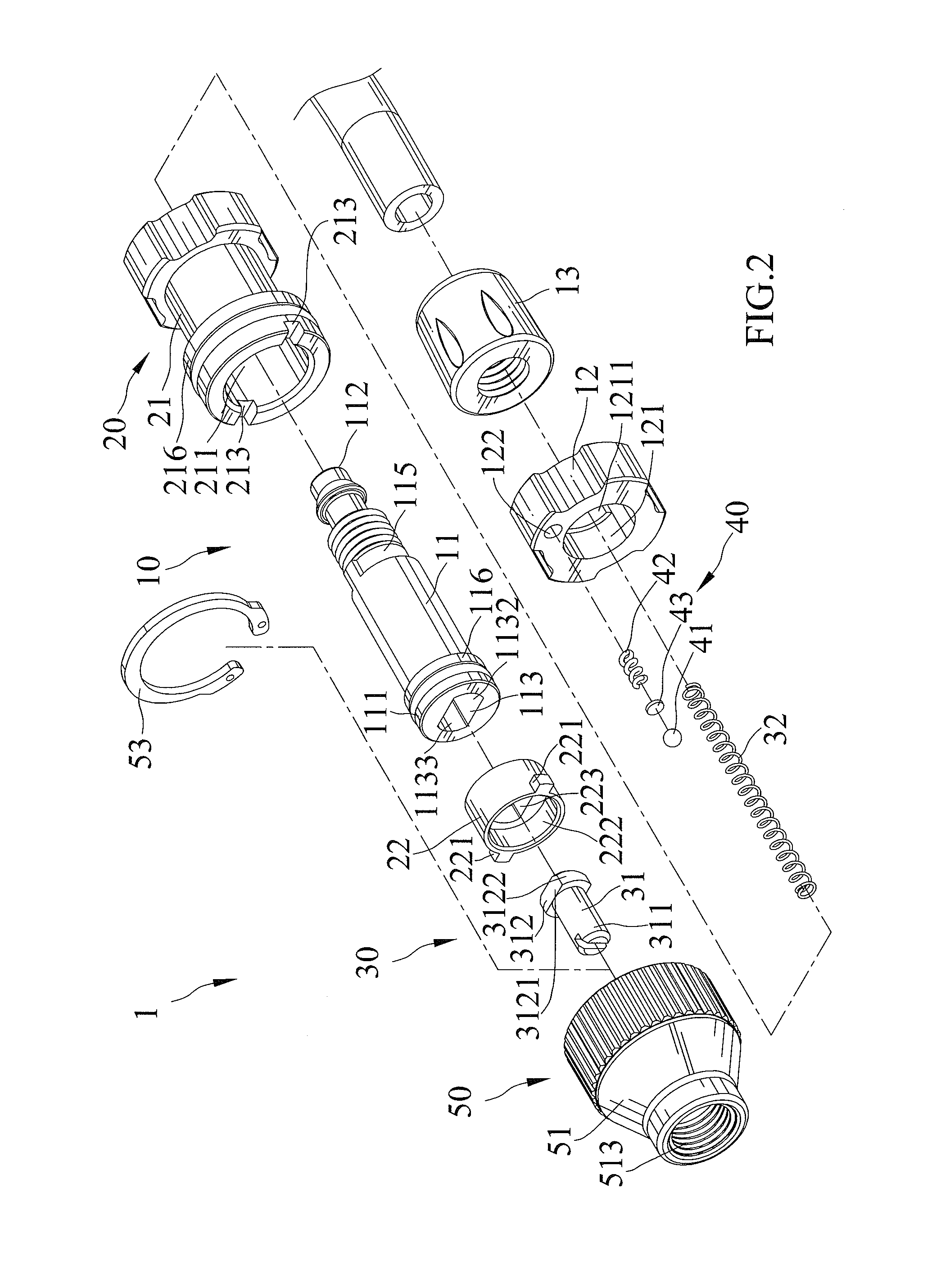
[0033]Referring to FIGS. 1 through 3, there is shown a nozzle device 1 according to the present invention, the nozzle device 1 comprises a body 10, a controller 20 mounted on the body 10, and a core set 30 slideably received in the body 10.

[0034]The body 10 includes a guiding member 11, a retainer 12 and a fastener 13. The guiding member 11 and the retainer 12 may be separately formed or may be integrally formed as one piece. The guiding member 11 has two opposing ends including a first end 111 and a second end 112. The first end 111 of the guiding member 11 has a chamber 113 formed thereon for receiving the core set 30. The second end 112 of the guiding member 11, which is adapted for coupling with an air pump or the like, has an aperture 114 formed thereon and in communication with the chamber 113. Preferably, the aperture 114 has an inner diameter smaller than that of the chamber 113. The guiding member 11 further has an engagement face 119 provided between the chamber 113 and th...

second embodiment

[0048]The nozzle device 1 in accordance with the second embodiment comprises a positioning mechanism 40a disposed between the switch 22a of the controller 20a and the guiding member 11a of the body 10a, in which the positioning mechanism 40a retains the controller 20a in one of the first and second positions. The positioning mechanism 40a includes a positioning unit 41a, an elastic member 42a and a plate 43a disposed between the positioning unit 41a and the elastic member 42a. Preferably, the switch 22a has a slot 224a provided on onside thereof adjacent to the guiding member 11a, and the guiding member 11a has a first cavity 117a and a second cavity 118a both provided on one side thereof adjacent to the switch 22a. The positioning mechanism 40a is installed to the slot 224a of the switch 11a with one end of the elastic member 42a abutted against the slot 224a and the other end of the elastic abutted against the plate 43a so as to longitudinally press the plate 43a and the positioni...


PUM


Abstract

A nozzle device comprises a body, a controller and a core set. The controller is pivotally mounted on the body and is pivotable with respect to the body between a first position and a second position. The core set is slideably received in the body. While the controller is in the first position, the core set is slideable in the chamber and is adapted for coupling with a French type valve. While the controller is in the second position, the core set is fixed and is adapted for coupling with an American type valve.

Description

BACKGROUND OF THE INVENTION[0001]1. Field of the Invention[0002]The present invention relates generally to a nozzle device for a pump and, more particularly, to a nozzle device for an air pump that can be used with valves of various types.[0003]2. Description of the Related Art[0004]U.S. Pat. No. 5,960,815 shows an inflating device which is provided with an air nozzle having two connectors of different specifications and engageable with inflation valves of different specifications. The air nozzle is composed of a shell, a distribution valve chamber located in the shell, an obstructing body located in the distribution valve chamber, and two connectors in communication with the distribution valve chamber. The conventional inflating device needs a large size shell for installation of the two connectors such that the shell might interfere with respect to a spoke while operation.[0005]U.S. Publication No. 2008 / 0236675 shows a an air valve connecting device which includes a mouth attached...

Claims


Application Information

Patent Timeline
IPC IPC(8): F16K15/20F16L37/00
CPCF16L37/00F04B33/005F16K15/20Y10T137/5196Y10T137/3724
Inventor WU, SCOTT
Owner WU NA
Why Eureka
Try Eureka