
Automatic GPS tracking system with passive or active battery circuitry

a tracking system and passive or active battery technology, applied in power management, instruments, high-level techniques, etc., can solve the problems of frequent battery charging or replacement, prior art necessitate constant battery consumption,

Inactive Publication Date: 2012-09-20
GHAZARIAN OHANES D
View PDF9 Cites 69 Cited by
  • Summary
  • Abstract
  • Description
  • Claims
  • Application Information

AI Technical Summary

Benefits of technology

[0025]The primary object of the present invention is to provide a GPS tracking system worn or installed on persons for tracking or assets with a global positioning receiver utilizing an RF transceiver to establish communication with a home base unit when the tracking system is located within proximity of a home base unit, the tracking unit is designed to generate warning signals when the person attached with a tracking unit wonders away from the proximity of RF communication range from the home base unit, to warn the user leave the RF communication proximity range of the home base unit, to avoid the tracking device from reporting, and alert the user to avoid the tracking device making unnecessary reports, save network call charges and save tracking device cellular or satellite module consuming battery, the unit utilizing two separate batteries for the power supply. The invention consists of a GPS tracking unit, having a processor, a GPS receiver and a satellite or cellular modem and a low power consumption RF transceiver, and a user warning alarm signaling circuitry. The GPS tracking unit utilizes a first battery for its power supply, communicating with an RF signal at time intervals with a home base station RF transceiver unit, located in a pre-selected area within the communication range of the GPS tracking unit.

Problems solved by technology

This prior art necessitates constant battery consumption, requiring frequent battery charging or replacement, in order for the GPS receiver to receive satellite signals, the comparator to function and the wireless modem to receive and transmit a signal.

Method used


Image

  • Automatic GPS tracking system with passive or active battery circuitry
  • Automatic GPS tracking system with passive or active battery circuitry
  • Automatic GPS tracking system with passive or active battery circuitry

Examples


Embodiment Construction

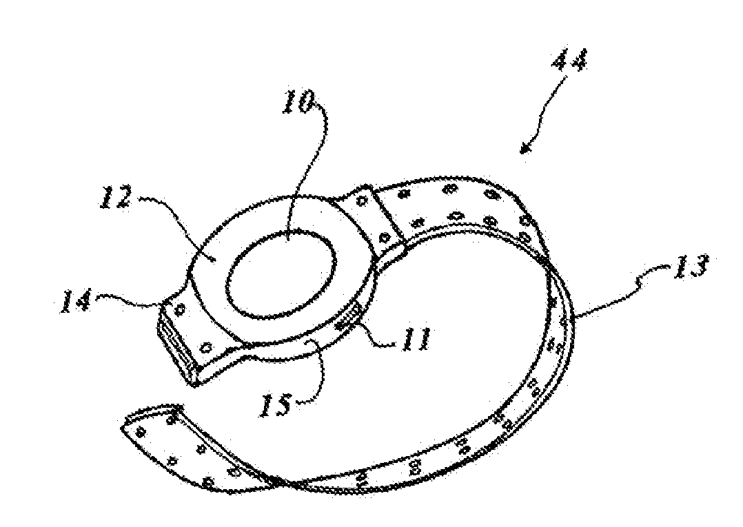
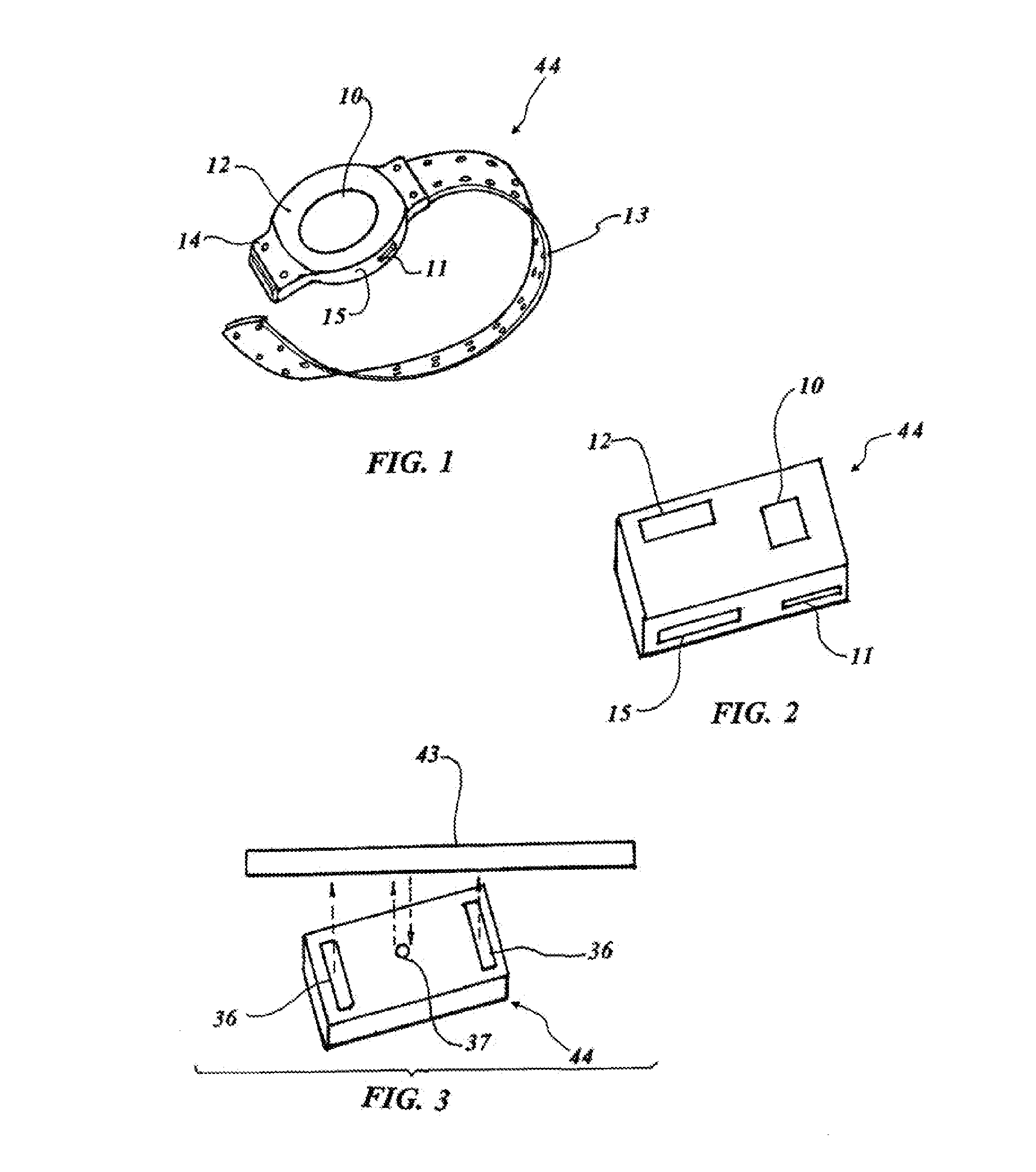
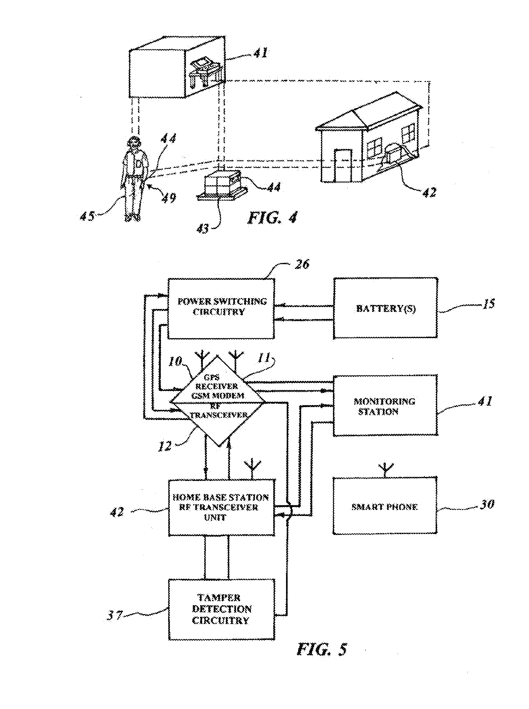
[0058]An embodiment of the GPS tracking system is shown in FIGS. 1 through 5 and is comprised of a portable battery operated GPS tracking unit 44 to be mounted on an asset 43 or attached to a person 45, such as the person's wrist or ankle 49, as can be seen in FIG. 4. Referring to FIGS. 1 and 2, the GPS tracking unit 44 may have a wearable configuration, an asset-attached configuration, among other configurations. The GPS tracking unit 44 may include a GPS receiver 10, and a cellular or satellite modem 11. Incorporated in the GPS tracking unit 44, may be a low power consumption RF transceiver 12 using a battery or dual batteries 15. The battery 15 may preferably be a Li-Ion rechargeable battery that provides power to the low power RF transceiver 12, and provides power to a GPS receiver 10 and a wireless communication modem 11 which are also included in the tracking unit 44. The low power consumption RF transceiver 12 may communicate at various predetermined time intervals with a hom...


PUM


Abstract

An automatic GPS tracking system consists of a GPS tracking unit secured to a person or an asset that includes a GPS receiver and a first battery powering a processor and first RF transceiver. A home base station receives the RF signal within a pre-selected proximity. A monitoring station which is in communication with the GPS tracking unit such that, if a person or asset having the tracking system secured thereon moves beyond the pre-selected proximity from a home base unit, the first transceiver RF communication signals is lost, and the processor activates an alerting device to indicate the GPS tracking unit is beyond the limited range of the home base station unit. When a second confirmation signal is not received from the home base station unit, a second battery is activated to power GPS receiver and the cellular modem to track the person or asset.

Description

CROSS REFERENCE TO RELATED APPLICATION[0001]This application is a continuation in part of U.S. patent application Ser. No. 12 / 001,937, filed Dec. 12, 2007, which is a continuation in part of U.S. patent application Ser. No. 11 / 411,164 filed Apr. 25, 2006.TECHNICAL FIELD[0002]The present invention relates to tracking of objects to provide location information. More specifically, the present invention relates to a GPS tracking device worn or securely attached on a person's limb or an asset. The GPS tracking device may utilize an RF transceiver designed to establish communication with a home base unit when the tracking system is located within proximity of a home base unit. The tracking unit may be designed to generate warning signals when the person attached with a tracking devise wanders behind the RF communication proximity range of the home base unit to warn the user is moving away from the home base unit RF communication proximity range, and to avoid the tracking system automatica...

Claims


Application Information

Patent Timeline
Patent Type & Authority Applications(United States)
IPC IPC(8): G01S19/12G01S19/34G08B21/22G01S19/16
CPCG01S19/16G01S19/34G08B13/1427G08B21/0202H04W52/0241G08B21/0269G08B21/0288G08B25/016H04L12/10G08B21/023Y02D30/70
Inventor GHAZARIAN, OHANES D.
Owner GHAZARIAN OHANES D
Learn More