
Recording apparatus

a recording device and recording medium technology, applied in the direction of printing, other printing devices, etc., can solve the problems of air leakage, air leakage, air leakage, etc., and achieve the effect of reducing the adsorption force of recording medium

Inactive Publication Date: 2012-09-20
SEIKO EPSON CORP
View PDF3 Cites 24 Cited by
  • Summary
  • Abstract
  • Description
  • Claims
  • Application Information

AI Technical Summary

Benefits of technology

[0011]An advantage of some aspects of the invention is to provide a recording apparatus which may suppress an increase in costs and reliably adsorb and retain a recording medium.

Problems solved by technology

In other words, since a suction hole in an open state, not covered by the recording medium, is present, air leaks from the suction hole (air leakage occurs).
In addition, if the number of suction holes in such an open state increases, the adsorption force for adsorbing the recording medium is deteriorated, and the uplift of the recording medium is imperfectly suppressed.
In JP-A-2002-205855, the outside air is sucked up through the plurality of suction holes formed in the platen, and the recording medium may be adsorbed to the surface of the platen, but the processing work for forming a plurality of adsorption holes in a plate which becomes the base material of the platen requires time or cost.

Method used


Image

  • Recording apparatus
  • Recording apparatus
  • Recording apparatus

Examples


first embodiment

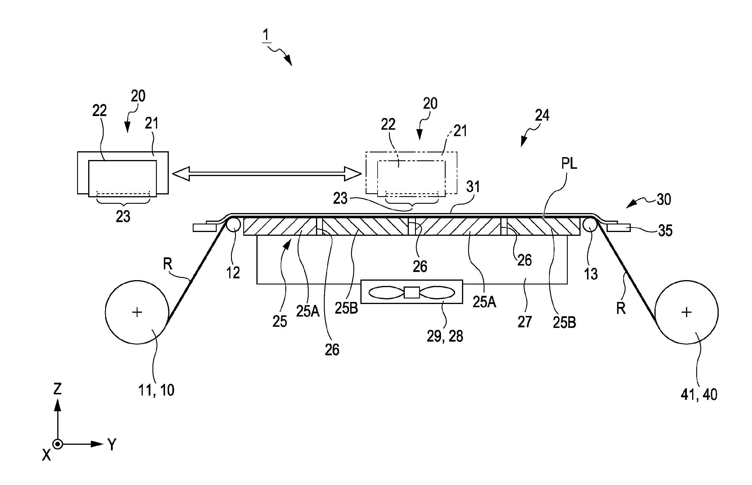
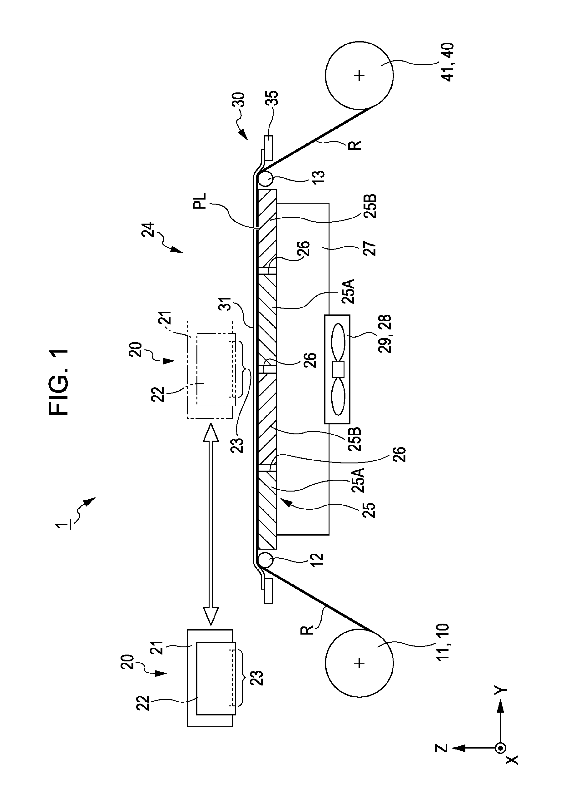
[0030]FIG. 1 is a side view showing a schematic configuration of an ink jet printer 1 according to this embodiment.

[0031]As shown in FIG. 1, the ink jet printer (a recording apparatus) 1 includes a transporting unit 10, a recording unit (a record processing unit) 20 and a discharging unit 40.

[0032]The transporting unit (a medium transporting unit) 10 is installed to transport a roll paper (recording medium) R, which is one example of a recording medium to the recording unit 20. In detail, a roll medium holder 11 is provided so that the roll medium holder 11 retains a roll-shaped roll paper R. In addition, by rotating the roll-shaped roll paper R, a first roller 12 is interposed to the recording unit 20 at a downstream side in the transporting direction (the arrow direction on the Y axis), and it is configured so that a roll paper R whose roll state is released may be transported.

[0033]The recording unit 20 is installed to discharge ink, which is an example of a liquid, to the roll p...


PUM


Abstract

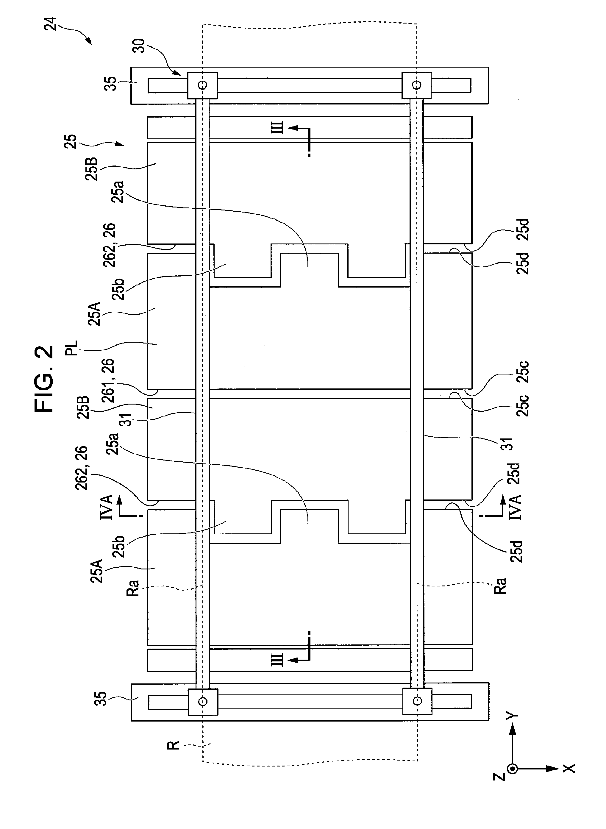
An ink jet printer includes a platen in which a plurality of plate members configuring a support surface supporting a roll paper are disposed at a predetermined interval so that suction grooves are formed between the plate members, a recording unit for performing a recording process on the roll paper placed on the support surface, a pressure chamber disposed at the back side of the platen and communicating with the suction grooves, and a suction mechanism for sucking up the roll paper disposed on the support surface through the suction grooves.

Description

INCORPORATION BY REFERENCE[0001]This Application claims the benefit of Japanese Patent Application No. 2011-061365, filed on Mar. 18, 2011, which is hereby incorporated by reference herein in its entirety.BACKGROUND[0002]1. Technical Field[0003]The present invention relates to a recording apparatus.[0004]2. Related Art[0005]In a recording apparatus such as an ink jet printer, when a recording process is performed on a recording medium such as a recording paper, the recording medium should be supported by a platen to have a predetermined posture (parallel) with respect to a recording head.[0006]In particular, in a case where a roll paper is used as the recording medium, since the end of the roll paper lifts up from the platen due to winding (curl), a paper suction unit for sucking up the roll paper may be provided at the platen in order to prevent the uplift.[0007]A plurality of suction holes is generally provided in the platen, and the paper suction unit sucks up the outside air thr...

Claims


Application Information

Patent Timeline
Patent Type & Authority Applications(United States)
IPC IPC(8): B41J2/01
CPCB41J11/0085B41J15/04B41J11/06
Inventor TOYA, AKIHIRO
Owner SEIKO EPSON CORP
Learn More