
Orthodontic bracket for use on deciduous teeth

a technology for orthodontic brackets and deciduous teeth, which is applied in dental surgery, dental tools, medical science, etc., can solve the problems of brittle brackets made of materials more brittle than metals, such as ceramics, that are not easily peeled or pried away from the tooth surface, and tend to fracture under applied force, so as to reduce the potential for damage to the tooth, minimize mechanical forces, and use anchors

Active Publication Date: 2012-09-20
MASHOUF CAMERON
View PDF7 Cites 3 Cited by
  • Summary
  • Abstract
  • Description
  • Claims
  • Application Information

AI Technical Summary

Benefits of technology

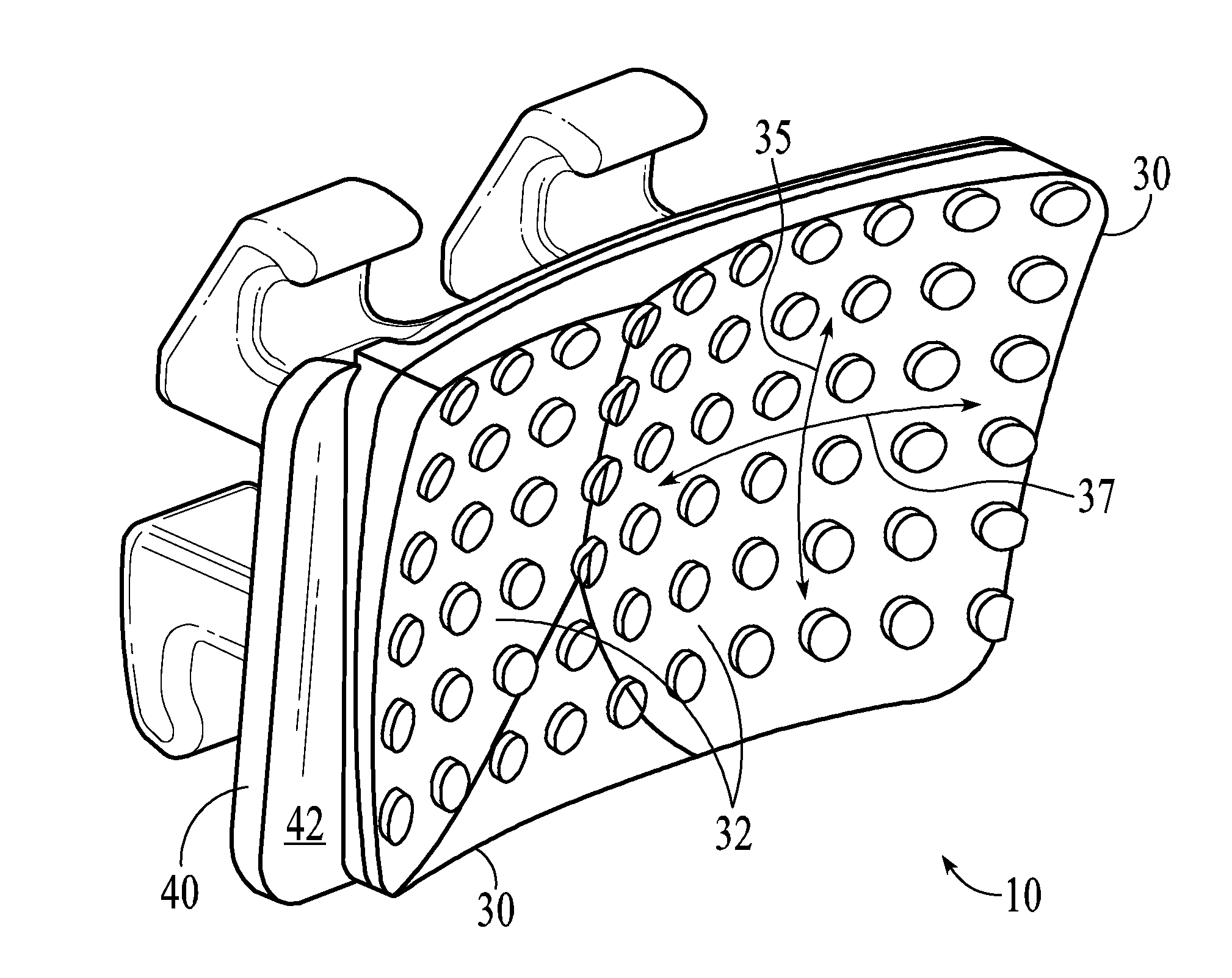
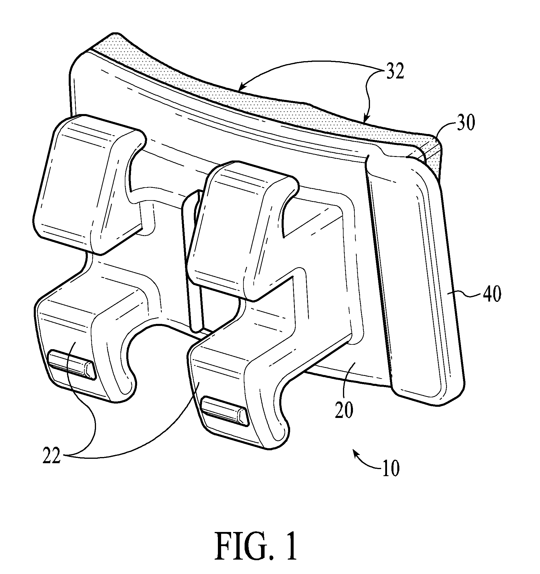
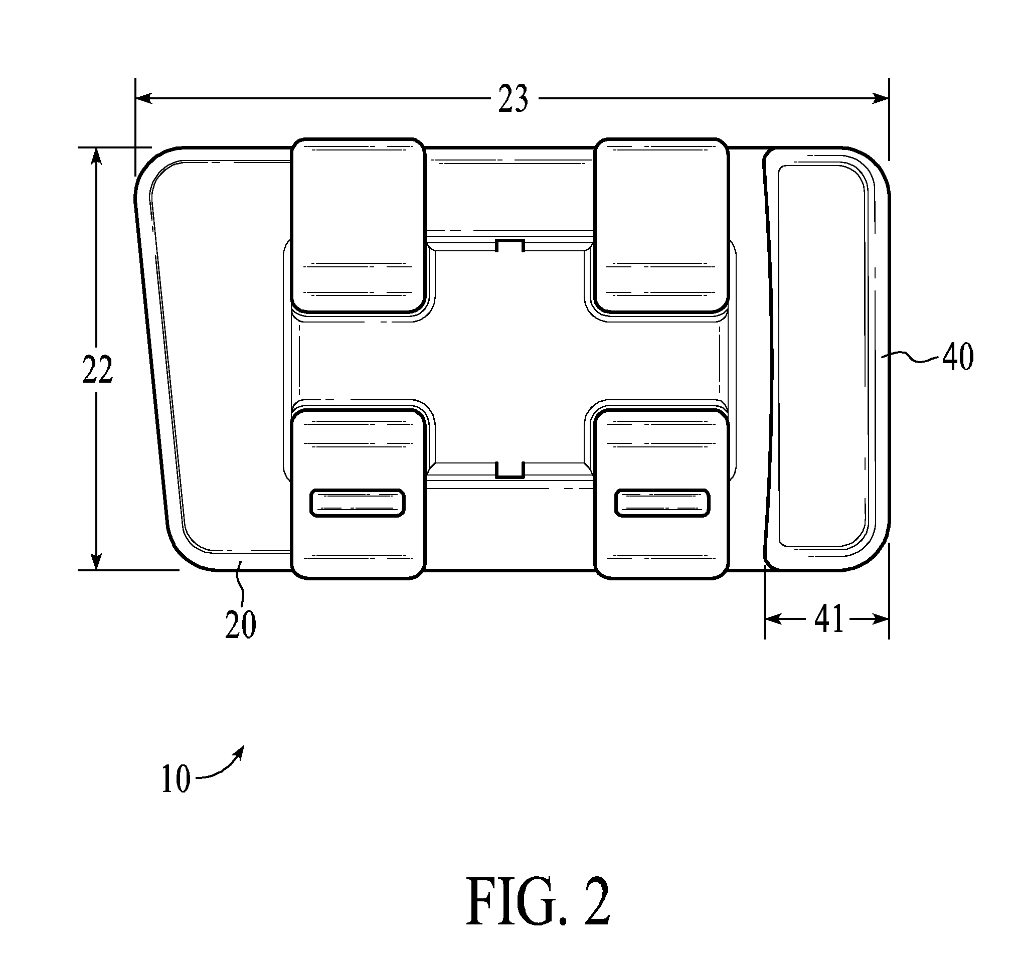
[0012]The present invention relates to an orthodontic bracket specifically designed for use with the deciduous teeth and method for its use. The deciduous teeth have been shown by various practitioners to be particularly useful anchors for the alignment of permanent teeth when integrated into a dental appliance. The bracket is unique in providing a debonding tab which reduces the potential for damage to the tooth due to the application of excessive force during the debonding process. The small size of the bracket allows it to fit available crown space on the deciduous teeth. Further the bracket is modified in shape to minimize mechanical forces applied to the deciduous teeth when engaged with an archwire. The bracket base is shaped to conform to the morphology of the deciduous crown surface thereby providing an optimal adhesive interface with the deciduous tooth. The deciduous bracket provides adequate adhesion to avoid unwanted detachment of the bracket which often occurs when the use of permanent brackets is attempted on the deciduous teeth.

Problems solved by technology

Brackets made of materials more brittle than metal, such as ceramic, are not easily peeled or pried away from the tooth surface and tend to fracture under an applied force.
An attempt to apply mesial-distal force as described with metal brackets generally results in the fracture of the tie wings or other portions of the bracket.

Method used


Image

  • Orthodontic bracket for use on deciduous teeth
  • Orthodontic bracket for use on deciduous teeth
  • Orthodontic bracket for use on deciduous teeth

Examples


Embodiment Construction

[0023]The following description is presented to enable any person skilled in the art to make and use the disclosed embodiments, and is provided in the context of a particular application and its requirements. Various modifications to the disclosed embodiments will be readily apparent to those skilled in the art, and the general principles defined herein may be applied to other embodiments and applications without departing from the spirit and scope of the present description. Thus, the present description is not intended to be limited to the embodiments shown, but is to be accorded the widest scope consistent with the principles and features disclosed herein.

[0024]For the purposes of this disclosure the term “deciduous bracket” refers to an orthodontic bracket particularly designed for use on a deciduous human tooth.

[0025]Orthodontic treatment is defined as correction of misaligned teeth and improper bite. Alignment of crooked teeth and correction of bite problems are accomplished b...


PUM


Abstract

The present invention relates to an orthodontic bracket specifically designed for use with the deciduous teeth and method for its use. The bracket is unique in providing a debonding tab which reduces the potential for damage to the tooth due to the application of excessive force during the debonding process. The small size of the bracket allows it to fit available crown space on the deciduous teeth. Further the bracket is modified in shape to minimize mechanical forces applied to the deciduous teeth when engaged with an archwire. The bracket base is shaped to conform to the morphology of the deciduous tooth crown surface thereby providing an optimal adhesive interface with the deciduous tooth. The deciduous bracket provides adequate adhesion to avoid unwanted detachment of the bracket which often occurs when the use of permanent brackets is attempted on the deciduous teeth.

Description

CROSS-REFERENCE TO RELATED PATENTSStatement Regarding Federally Sponsored Reasearch or DevelopmentThe Names of the Parties to a Joint Research AgreementFIELD OF THE INVENTION[0001]This invention relates to the use of orthodontic brackets on deciduous teeth to correct tooth alignment.BACKGROUND OF THE INVENTION[0002]One type of common orthodontic treatment involves the use of a set of tiny appliances commonly known as brackets and buccal tubes. Buccal tubes are normally mounted on the molars and brackets are attached to all other teeth. Each bracket is secured to a corresponding tooth through a bonding adhesive which is sandwiched between the pad of bracket on one side and enamel surface of the tooth on the other side. Each bracket has a slot to receive a resilient archwire. The slot forms a track to guide movement of the teeth to desired positions. Ends of archwire are commonly placed in slots or channels of buccal tube appliances that are attached to the molar teeth either through ...

Claims


Application Information

Patent Timeline
IPC IPC(8): A61C7/28
CPCA61C7/14A61C7/023A61C7/16
Inventor MASHOUF, CAMERON
Owner MASHOUF CAMERON
Learn More