
Conically tapered dental implant

a dental implant and implant technology, applied in dentistry, dental surgery, medical science, etc., can solve the problems of inability to properly protect food, inability to fit a provisional protective tooth (made of plastic, for example) on the adjacent teeth by metal clips, and space arises

Inactive Publication Date: 2012-09-20
ANTHOGYR
View PDF30 Cites 12 Cited by
  • Summary
  • Abstract
  • Description
  • Claims
  • Application Information

AI Technical Summary

Benefits of technology

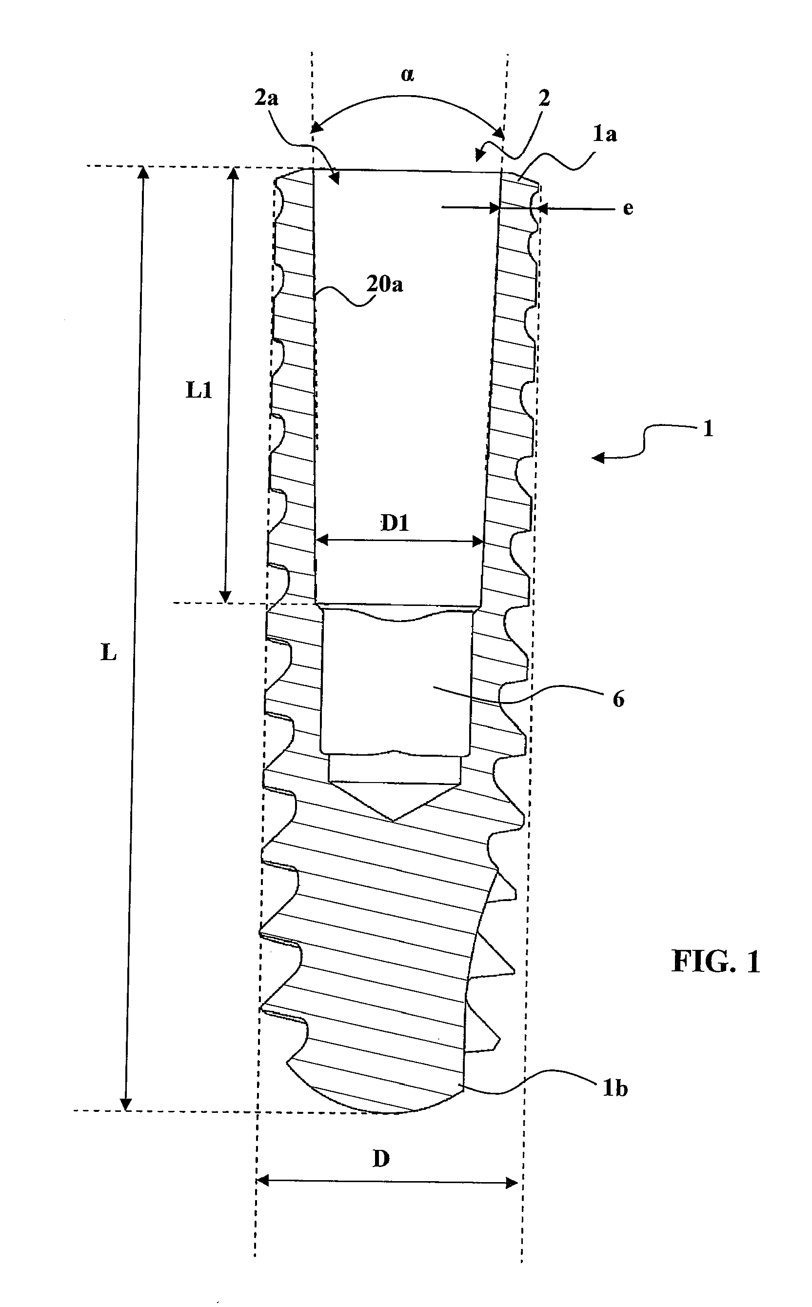
[0017]A conically tapered fit of this kind avoids constant thinning along a considerable height of the dental implant and efficiently limits the stress concentrations which are most often the cause of rupturing of the connection between a final abutment and a dental implant of the type described in the document EP 1 849 431.
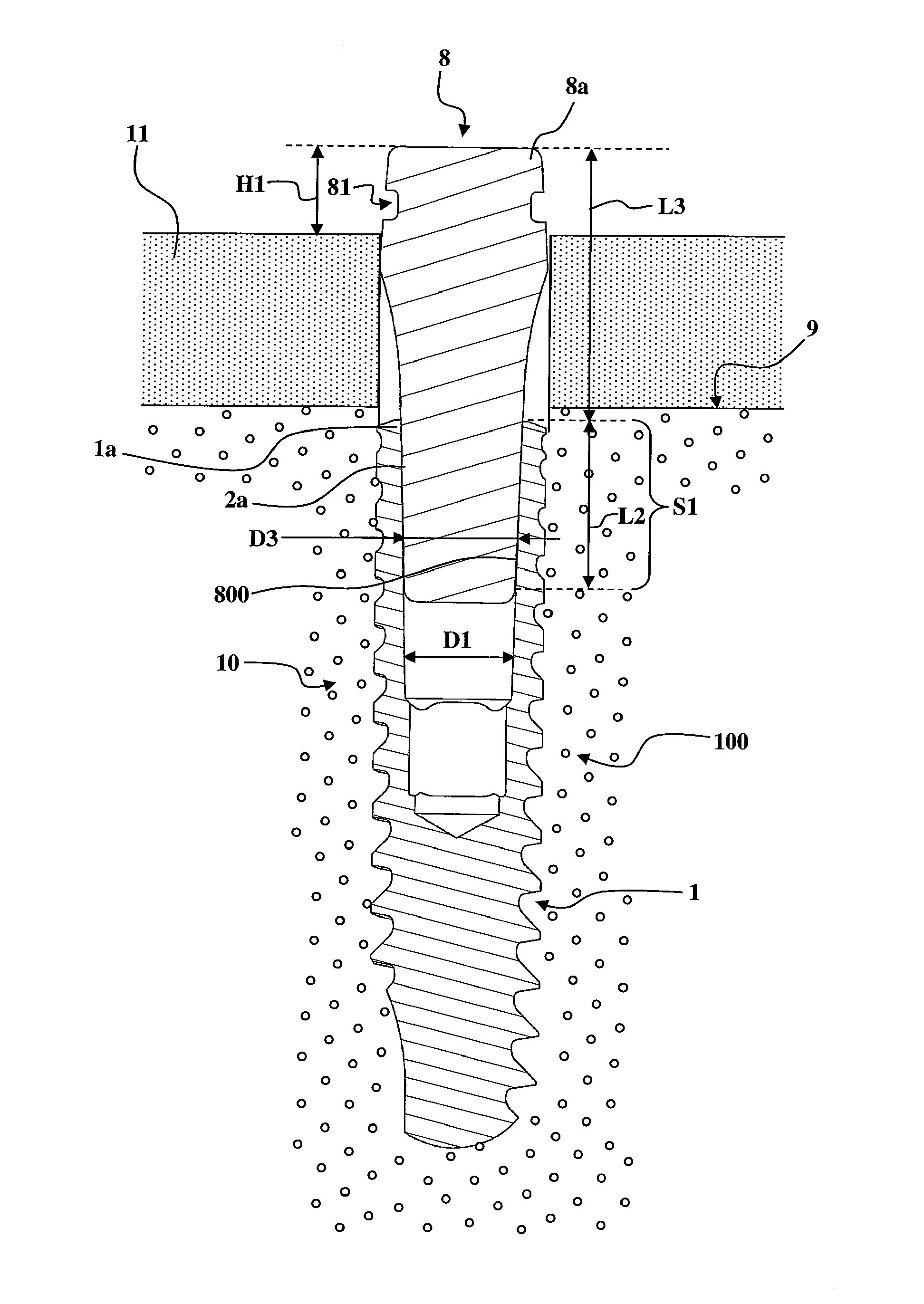
[0048]Such a protrusion of the cicatrization component above the distal connection end of the dental implant makes it possible to fit in place, above the cicatrization component, protective means such as a provisional protective tooth made of plastic and secured on the adjacent teeth by metal clips. However, this protrusion still permits gripping by an extraction tool for removal of the cicatrization component.

Problems solved by technology

When replacing a tooth by a prosthesis, a problem often arises in obtaining sufficient interdental space for insertion of a dental implant between two teeth.
This problem of space arises very particularly when replacing the mandibular incisors or maxillary lateral incisors, especially in cases of agenesis.
With this type of one-piece dental implant, a problem arises between the surgical step of inserting the dental implant into the bone of the jaw and the step of fitting the tooth prosthesis in place on the prosthesis support provided by the abutment.
However, the abutment protrudes above the gum and cannot be correctly protected from food during mastication.
The protrusion of the abutment makes it impossible to fit a provisional protective tooth (made of plastic, for example) secured on the adjacent teeth by metal clips.
The problem with this type of dental implant, combined with an attached final abutment, is that the material thickness around the internally threaded female cavity and the diameter of the screw intended to be inserted therein are too small to be able to mechanically withstand the high occlusal loads of mastication, which can be as high as approximately 222 N near the incisors, especially when the dental implant has a maximum external diameter of less than 3 mm along the entire length thereof.

Method used


Image

  • Conically tapered dental implant
  • Conically tapered dental implant
  • Conically tapered dental implant

Examples


example

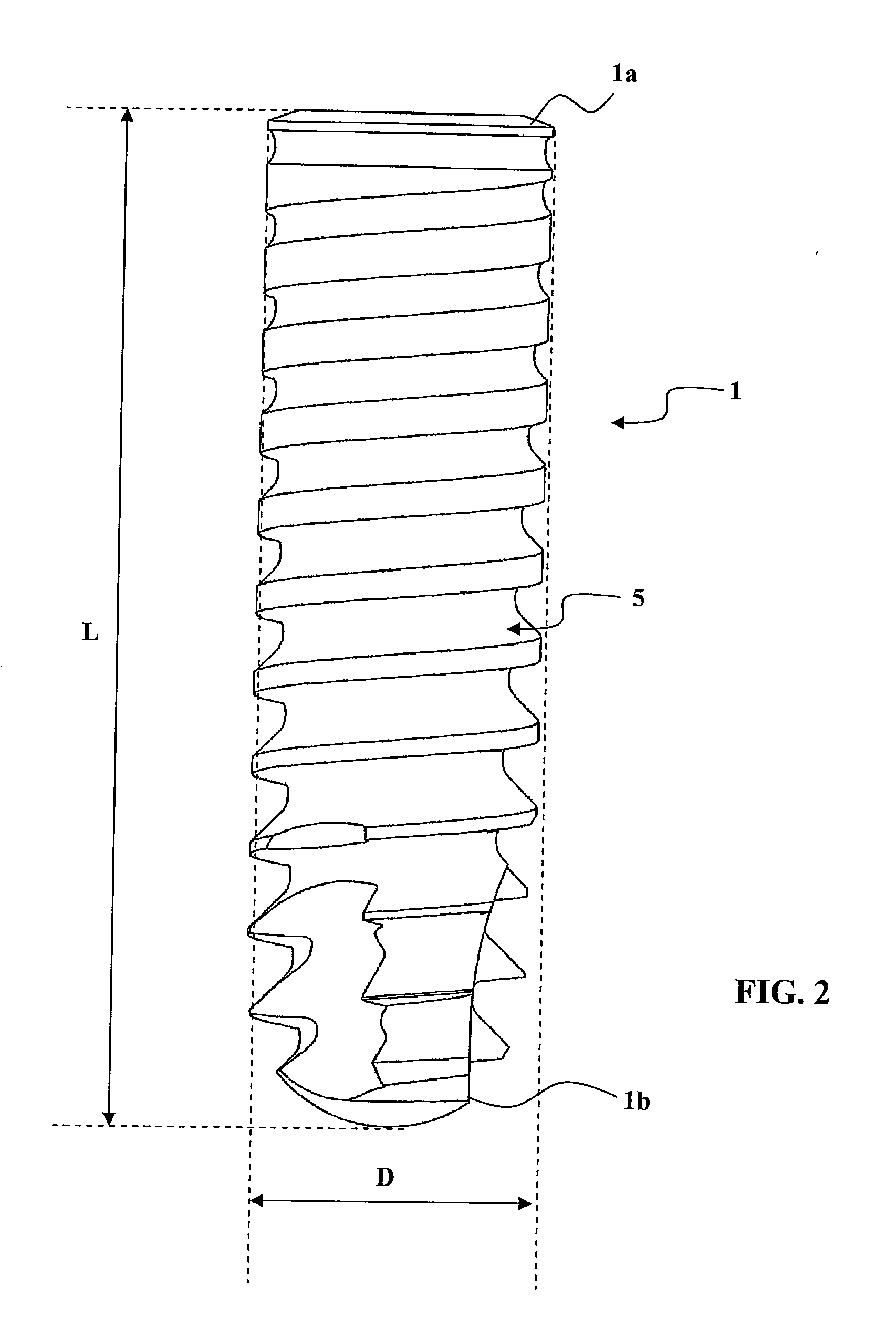
[0084]A dental implant 1 according to the invention was produced with the following parameters:

L=14 mm

D=2.8 mm

[0085]α=β3=30

L1=4.6 mm

L3=4 mm

[0086]material: T60 (unalloyed titanium)

[0087]Three examples of this dental implant 1, each equipped with a final abutment 3, were subjected to repeated cycles of application of a dynamic force of 265 N according to ISO 14801. These dental implants 1 did not break until after more than 2 700 000 cycles. Excellent results were also obtained with alloyed titanium, for example TA6V.

[0088]The same cycles were applied, under the same conditions, to examples of an “OsseoSpeed® 3.0 S” implant, which is sold by the company ASTRA TECH FRANCE, is made of titanium T60 and has a maximum external diameter of 3 mm. The connection between the final abutment and the dental implant is ensured by a screwed connection. The screwed connection was broken after approximately 225 cycles.

[0089]Different kinds of final abutments can be used, as are illustrated in FIGS. 4...


PUM


Abstract

A dental implant (1) is intended to be inserted into the maxillary or mandibular bone of a patient, extending between a distal connection end (1a) and a proximal anchoring end (1b). The dental implant (1) has a maximum outside diameter (D) less than 3 mm over its entire length (L) and is provided with a receiving device (2) having a conically tapered female cavity (2a).

Description

TECHNICAL FIELD OF THE INVENTION[0001]The present invention relates to the field of tooth prostheses and more particularly to a dental implant intended to be inserted into the maxillary or mandibular bone of a patient. The present invention also relates to a temporary cicatrization component and a final abutment, which are designed to cooperate with said dental implant.[0002]When replacing a tooth by a prosthesis, a problem often arises in obtaining sufficient interdental space for insertion of a dental implant between two teeth.[0003]This problem of space arises very particularly when replacing the mandibular incisors or maxillary lateral incisors, especially in cases of agenesis. It is then necessary to use a dental implant of small external diameter so as to be able to insert it and screw it in between two teeth.[0004]The tooth prosthesis is mounted on a prosthesis support at the upper end of a final abutment connected to the dental implant. Since the forces of mastication can re...

Claims


Application Information

Patent Timeline
IPC IPC(8): A61C8/00
CPCA61C8/0022A61C8/005A61C8/008A61C8/0069A61C8/0071A61C8/0066
Inventor LANCIEUX, CEDRICPRIOU, CATHERINE
Owner ANTHOGYR
Learn More