

Ultrasound diagnostic apparatus and method of producing ultrasound image
a diagnostic apparatus and ultrasound technology, applied in tomography, instruments, applications, etc., can solve the problems of increasing the temperature of the ultrasound probe housing, causing the patient to feel discomfort, and reducing the spatial resolution
- Summary
- Abstract
- Description
- Claims
- Application Information
AI Technical Summary
Benefits of technology
Problems solved by technology
Method used
Image

Examples
embodiment 1
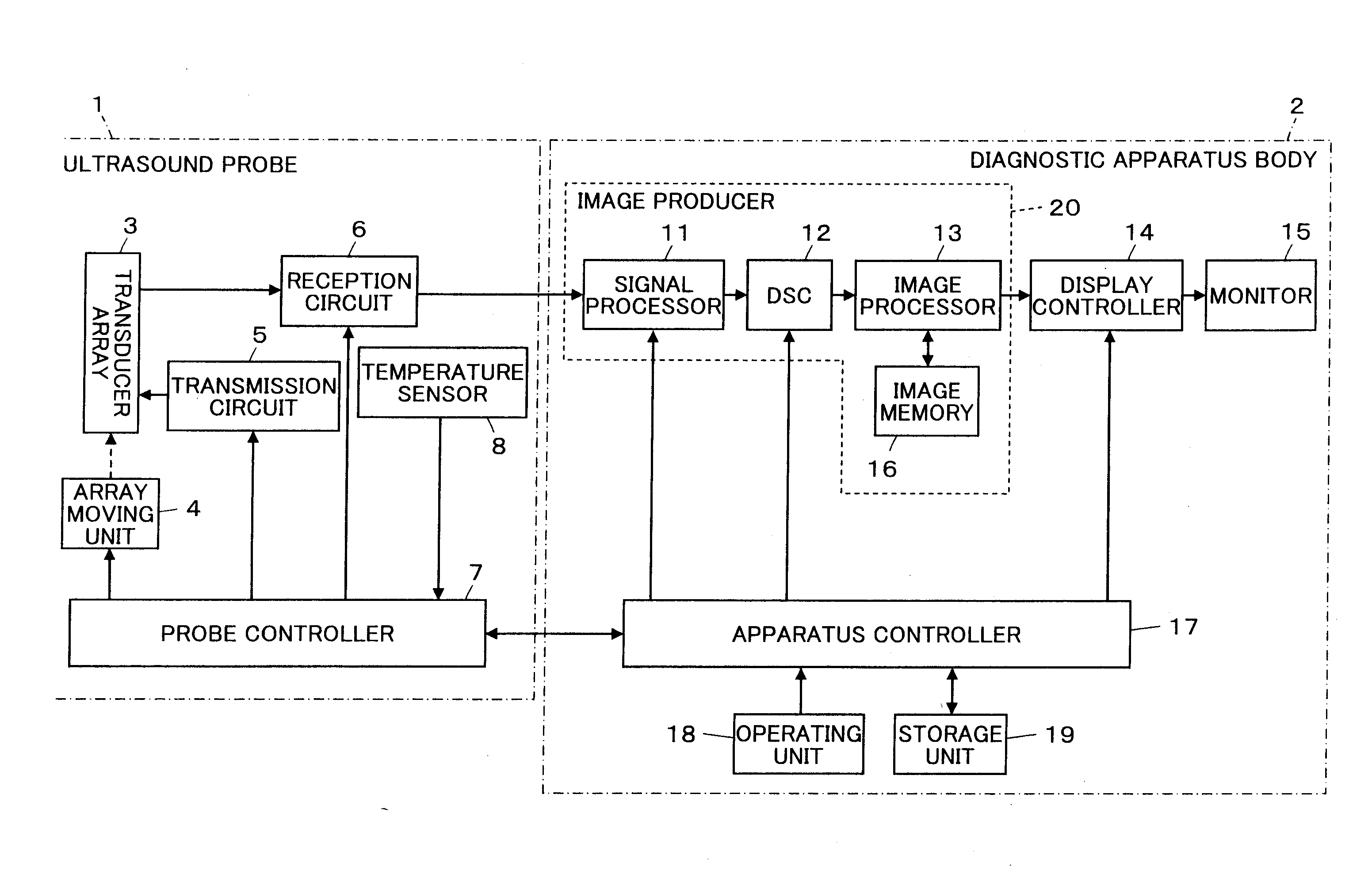
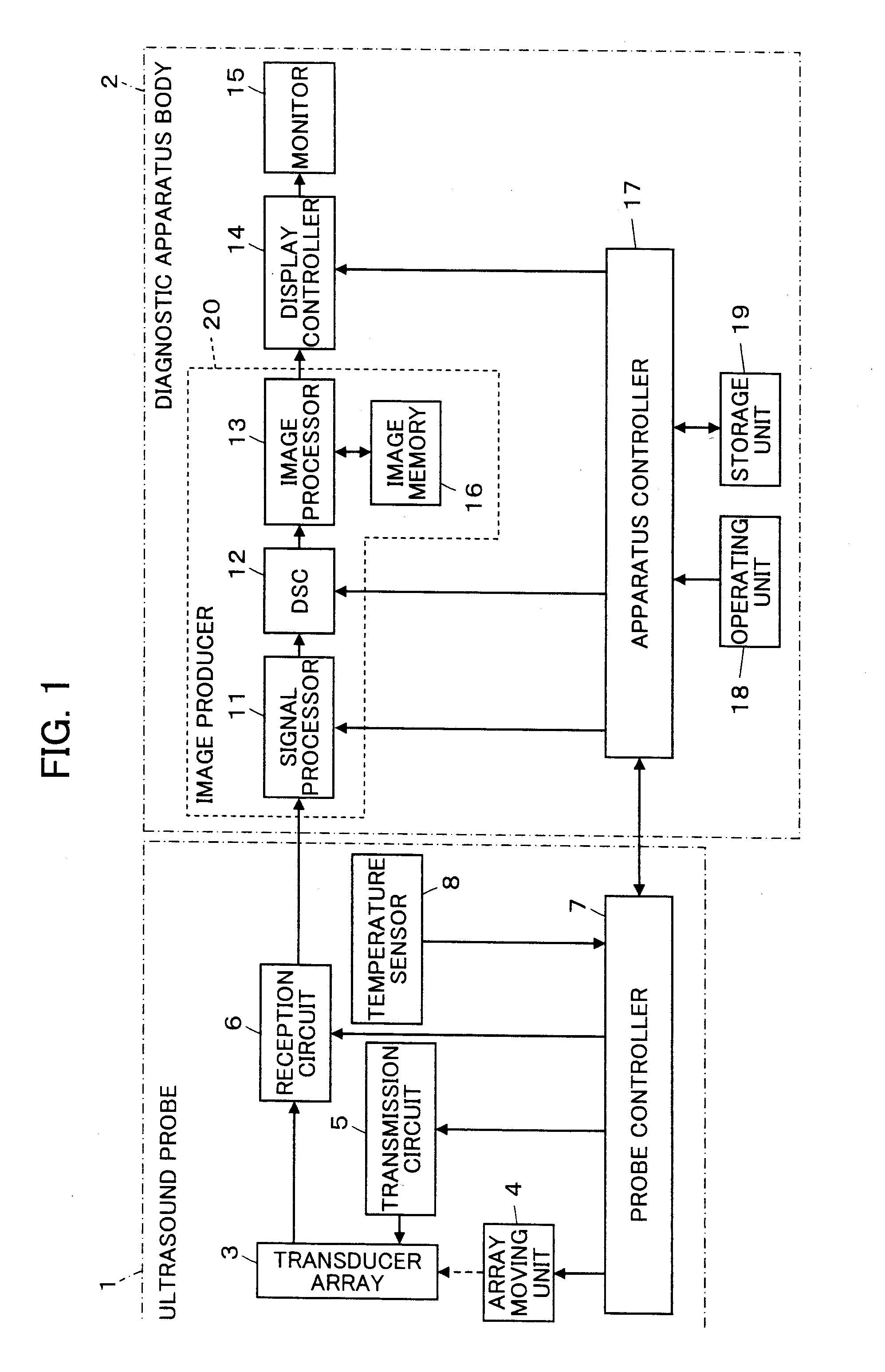
[0075]FIG. 1 shows the configuration of an ultrasound diagnostic apparatus according to Embodiment 1 of the invention. The ultrasound diagnostic apparatus includes an ultrasound probe 1, and a diagnostic apparatus body 2 connected to the ultrasound probe 1.
[0076]The ultrasound probe 1 has a transducer array 3 having a plurality of ultrasound transducers arranged one-dimensionally. An array moving unit 4 is connected to the transducer array 3, and a transmission circuit 5 and a reception circuit 6 are also connected to the transducer array 3. A probe controller 7 is connected to the array moving unit 4, the transmission circuit 5, and the reception circuit 6. A temperature sensor 8 which detects the internal temperature of the ultrasound probe 1 is embedded in the ultrasound probe 1, and the temperature sensor 8 is connected to the probe controller 7. The temperature sensor 8 is disposed, for example, in the vicinity of the reception circuit 6 where heat is expected to be generated, ...
embodiment 2
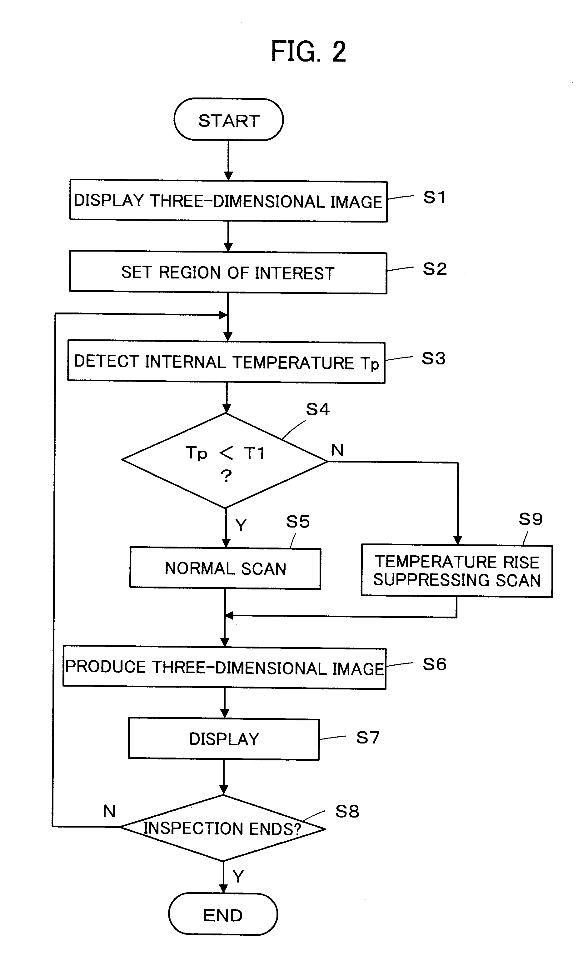
[0112]Although in Embodiment 1 described above, the first set value T1 is set, and when the internal temperature Tp of the ultrasound probe 1 is equal to or higher than the first set value T1, the temperature rise suppressing scan is performed, a plurality of temperature set values may be set, and scan having different temperature rise suppressing effects may be performed in a stepwise manner depending on the internal temperature Tp of the ultrasound probe 1.
[0113]For example, a second set value T2 higher than the first set value T1 and a third set value T3 higher than the second set value T2 are set in advance, and when the internal temperature Tp of the ultrasound probe 1 detected by the temperature sensor 8 is equal to or higher than the first set value T1 and lower than the second set value T2, as shown in FIG. 4, in the mechanical scan direction of the transducer array 3, electronic scan planes E are formed only in a range of the length Xv including the region V of interest. Wh...
embodiment 3
[0119]Although in Embodiment 1 described above, when the internal temperature Tp of the ultrasound probe 1 is equal to or higher than the first set value T1 and lower than the second set value T2, as shown in FIG. 4, the transmission and reception of an ultrasonic beam for a region other than the region V of interest in the X-axis direction which is the mechanical scan direction of the transducer array 3 is paused, the invention is not limited thereto. For example, as shown in FIG. 8, electronic scan planes E may be formed only in a range of the length Yv including the region V of interest in the Y-axis direction which is the one-dimensional array direction of the transducer array 3, and the transmission and reception of an ultrasonic beam for a region other than the region V of interest in the Y-axis direction may be paused.
[0120]In this case, a plurality of temperature set values are set, and when the internal temperature Tp of the ultrasound probe 1 increases to be equal to or hi...
PUM
 Abstract
Description
Claims
Application Information