Image data generating apparatus, method and program

Active Publication Date: 2010-06-17
PANASONIC INTELLECTUAL PROPERTY CORP OF AMERICA
View PDF6 Cites 12 Cited by
  • Summary
  • Abstract
  • Description
  • Claims
  • Application Information

AI Technical Summary

Benefits of technology

[0029]An apparatus according to the present invention separates incoming light that has come from a subject into a number of wavelength ranges, receives a portion of the split light that falls within a wavelength range with the highest luminosity factor, thereby getting a first image, receives the rest of the light that falls within the remaining wavelength ranges, other than the one with the highest luminosity factor, thereby getting a second image that has a lower spatial resolution, and a higher temporal resolution, than the first image, and converts the temporal resolution of the first image into that of the second image using the first and second images. By separating

Problems solved by technology

However, if the user wants to shoot the scene before him or her as finely as possible, he or she often opts for the highest possible spatial and temporal resolutions, thus making the data size of the picture huge.
However, wi

Method used


Image

  • Image data generating apparatus, method and program
  • Image data generating apparatus, method and program
  • Image data generating apparatus, method and program

Examples


embodiment 1

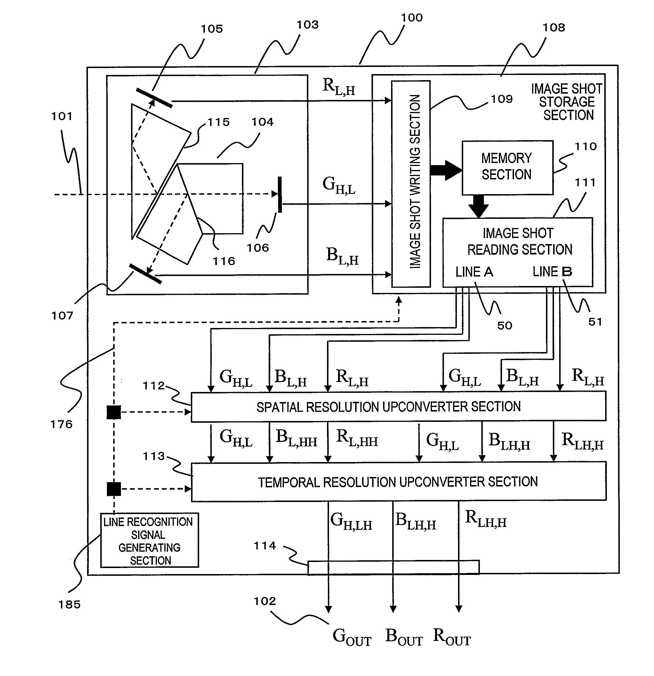
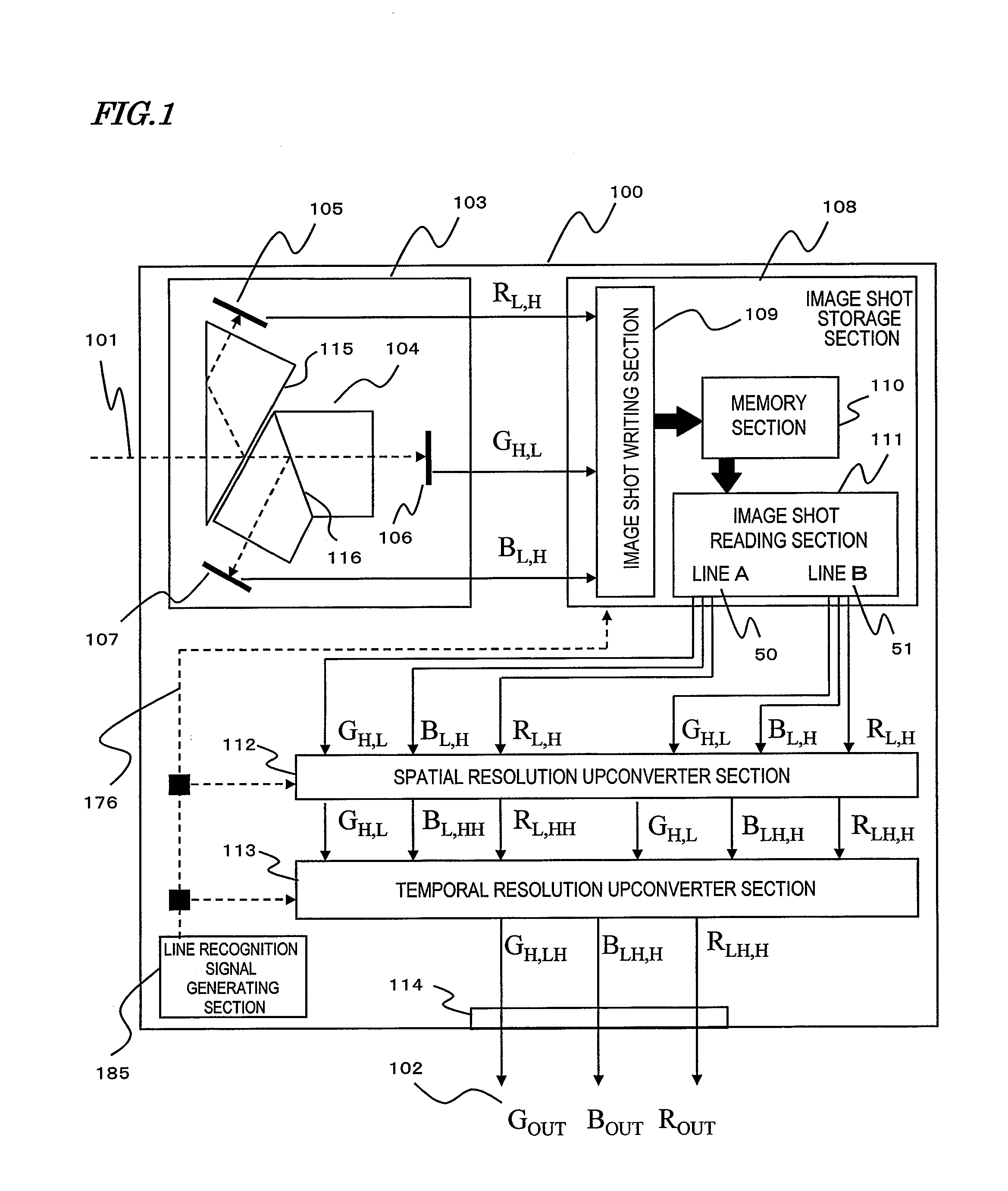
[0079]FIG. 1 is a block diagram illustrating a shooting, recording and playback system 100 as a first specific preferred embodiment of the present invention.

[0080]the Shooting, Recording and Playback System 100 receives incoming light 101, stores an image shot, and then subjects the image shot to be reproduced to resolution raising processing, thereby outputting RGB images with high spatial resolution and high temporal resolution (ROUT GOUT BOUT) 102. The shooting, recording and playback system 100 captures and stores a first image with high spatial resolution and low temporal resolution in a wavelength range with the highest luminosity factor (i.e., the green (G) wavelength range) and a second image with low spatial resolution and high temporal resolution in the other wavelength ranges (i.e., the red (R) and blue (B) wavelength ranges), respectively. Then, the system 100 converts the temporal resolution of the first image into that of the second image in accordance with the corresp...

embodiment 2

[0130]A second specific preferred embodiment of the present invention to be described below is a shooting, recording and playback system that shoots and records a first image with high spatial resolution and low temporal resolution in the G wavelength range with the highest luminosity factor and a second image with low spatial resolution and high temporal resolution in the other R and B wavelength ranges, respectively, converts the temporal resolution of the first image into that of the second image in accordance with the correspondence between the low- and high-spatial-resolution images and plays the image with the converted temporal resolution. The system can synthesize together a number of images with high spatial resolution and high temporal resolution in a luminance / color difference space, thus generating an image of quality with their color balance maintained.

[0131]FIG. 12 is a block diagram illustrating a configuration for a shooting, recording and playback system 200 as a se...

embodiment 3

[0136]A third specific preferred embodiment of the present invention to be described below is a shooting, recording and playback system that shoots and records a first image with high spatial resolution and low temporal resolution in the G wavelength range with the highest luminosity factor and a second image with low spatial resolution and high temporal resolution in the other R and B wavelength ranges, respectively, converts the temporal resolution of the first image into that of the second image in accordance with the correspondence between the low- and high-spatial-resolution images and plays the image with the converted temporal resolution. The system can synthesize together a number of images with high spatial resolution and high temporal resolution in a luminance / color difference space, thus generating an image of quality with their color balance maintained. By making a number of pixels share the same color difference component, luminance / color difference images with high spa...


PUM


Abstract

The shooting, recording and playback system 100 of the present invention receives incoming light 101, stores an image shot, and then subjects the image shot to be reproduced to resolution raising processing, thereby outputting RGB images with high spatial resolution and high temporal resolution (ROUT GOUT BOUT) 102. The system 100 includes a shooting section 103, a color separating section 104, an R imaging sensor section 105, a G imaging sensor section 106, a B imaging sensor section 107, an image shot storage section 108, an image shot writing section 109, a memory section 110, an image shot reading section 111, a spatial resolution upconverter section 112, a temporal resolution upconverter section 113, an output section 114, and a line recognition signal generating section 185. The system can get image data with high spatial resolution and high temporal resolution without getting the camera configuration complicated and without decreasing the optical efficiency.

Description

TECHNICAL FIELD[0001]The present invention relates to an apparatus and method for capturing a high-resolution image at a high frame rate, an apparatus and method for capturing, recording and playing such an image at a high frame rate, and a program for capturing and recording such an image at such a rate.BACKGROUND ART[0002]Recently, a digital camcorder or digital still camera has come to have an imager, including photosensing elements at tremendously high densities, and have had their definitions increased by leaps and bounds. Generally speaking, the higher the resolution of an image captured, the more finely the user can record the scene before him or her. That is why there is an increasing demand for such high-resolution shooting.[0003]The resolutions are classifiable into the spatial resolution and the temporal resolution. The resolution of the former type corresponds to the number of pixels that make up a single picture. If there are two imaging sensors of the same size but wit...

Claims


Application Information

Patent Timeline
IPC IPC(8): H04N9/68H04N9/09H04N5/232H04N5/335H04N9/04
CPCH04N5/2258H04N5/23232H04N9/097H04N9/09H04N9/045H04N9/64H04N23/45H04N23/951H04N23/16H04N23/13
Inventor MOTOMURA, HIDETOAZUMA, TAKEONOBORI, KUNIOIMAGAWA, TARO
Owner PANASONIC INTELLECTUAL PROPERTY CORP OF AMERICA
Why Eureka
Try Eureka