Radiographic equipment

A technology of radiography and equipment, applied in the exploration of nuclear radiation, material analysis using radiation, material analysis using wave/particle radiation, etc. complex problems, to achieve a good distinction

Inactive Publication Date: 2008-02-20
COMMONWEALTH SCI & IND RES ORG
View PDF1 Cites 23 Cited by
  • Summary
  • Abstract
  • Description
  • Claims
  • Application Information

AI Technical Summary

Problems solved by technology

However, the practical application of this technology for scanning items such as luggage is limited
The relatively low brightness of readily available neutron sources compared to X-ray sources, and the generally low spatial resolution and detection efficiency of neutron detectors compared to X-ray detectors
Neutron detectors that provide energy discrimination are complex and rely on nanosecond time-of-flight measurements or despectral techniques to infer the incident neutron energy spectrum
As a result, neutron radiography systems are generally too slow, have extremely poor spatial resolution and insufficient material discrimination capabilities to form the basis of actual luggage or package scanners

Method used


Image

  • Radiographic equipment
  • Radiographic equipment
  • Radiographic equipment

Examples


Embodiment Construction

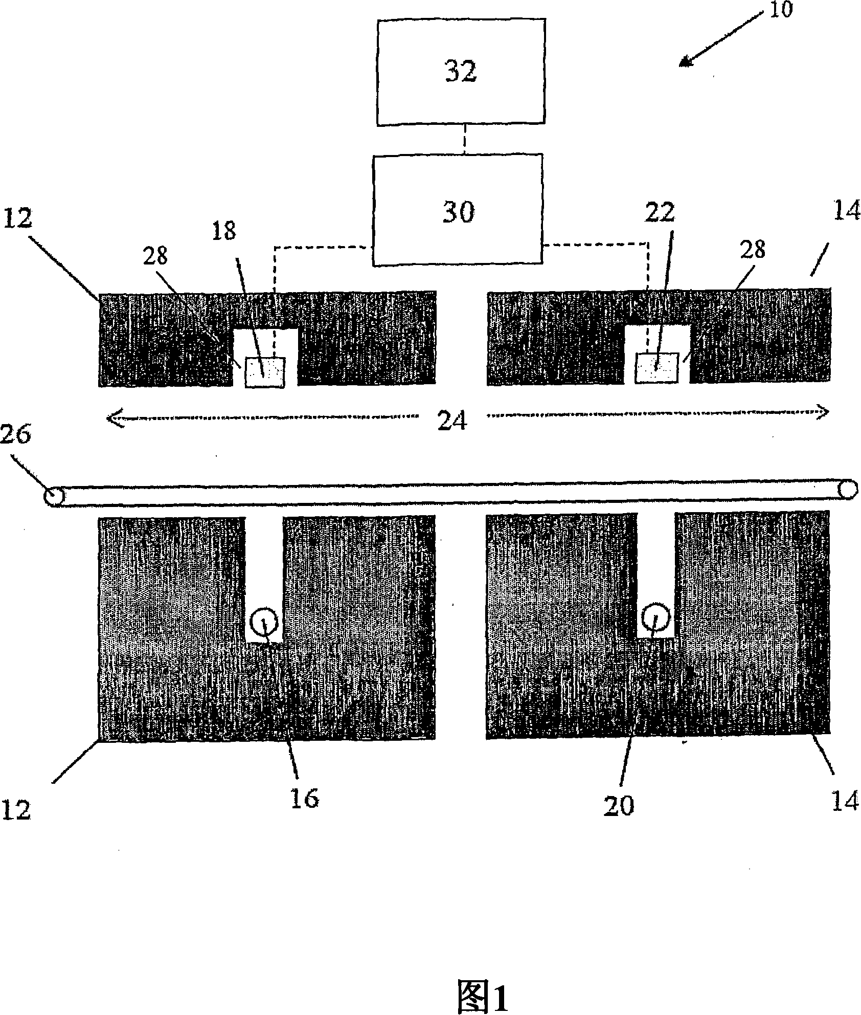
[0048] Figure 1 illustrates a radiographic apparatus 10 for forming images of an object in the form of a suitcase (not shown). Apparatus 10 includes a pair of shielding blocks 12 and 14 . The shield block 12 includes an X-ray tube source 16 capable of generating dual-energy X-rays and a dual-energy X-ray detector 18 . Shield block 14 contains 252 Cf neutron source 20 and neutron detector 22. A tunnel 24 passes through the shielding blocks 12 and 14 , and a conveyor belt 26 passing through the tunnel 24 is used to transport suitcases and other similar objects through the apparatus 10 .

[0049] Grooves 28 in shield blocks 12 and 14 define fan beams of X-ray and neutron radiation incident on detectors 18 and 22, respectively. Advantageously, in addition to confining the radiation beam, shield blocks 12 and 14 also provide radiation shielding, preventing the operator of apparatus 10 from being exposed to radiation.

[0050] The X-ray tube 16 is operated at a high voltage such...


PUM


Abstract

The invention concerns radiographic equipment for forming an image of an interior of an object. The equipment comprises a source of X-ray or gamma-ray radiation having two or more energies and operable to irradiate an object to be scanned and a radiation source producing neutrons operable to irradiate the object. The equipment also comprises a radiation detector array having a plurality of pixels, each sensitive to and arranged with respect to the X-ray or gamma-ray radiation source and the neutron producing radiation source and operable to measure the intensity of each type of radiation transmitted through the object; means to process the intensity of each type of radiation, to determine the attenuation of each type of radiation having passed through the object, and to form an image indicative of the shape and composition of the object's interior.

Description

technical field [0001] The present invention relates to radiographic apparatus and methods for forming images of the interior of an object. In particular, the present invention relates to radiographic equipment for detecting concealed objects, substances and materials such as in aircraft luggage, parcels and the like. Background technique [0002] In 1895, X-ray radiography was first demonstrated by Röntgen, in which the attenuation of X-rays is measured between a source located on one side of the object to be inspected and a fluorescent screen or detector on the opposite side. Images can be readily obtained, representing the size and shape of objects within a suitcase or containment. X-ray images can be easily obtained with good spatial resolution, representing fine details of the scanned object. However, the composition of these objects cannot be determined using a single X-ray energy. [0003] Efficient and well-known improvements include the acquisition of two separat...

Claims


Application Information

Patent Timeline
Patent Type & Authority Applications(China)
IPC IPC(8): G01N23/087G01N23/09
CPCG01V5/0041G01V5/0033
Inventor 布赖恩·大卫·索维比詹姆斯·理查德·蒂克纳格雷戈里·约翰·罗奇
Owner COMMONWEALTH SCI & IND RES ORG
Why Eureka
Try Eureka