Image Generating Apparatus and Method

a technology which is applied in the field of image generating apparatus and image generating method, can solve the problems of not being able to reliably delete noise portions, unable to remove noise portions less than a certain size, and unable to remove noise portions. achieve the effect of higher synthesizing ra

Inactive Publication Date: 2009-08-20
KEYENCE
View PDF4 Cites 18 Cited by
  • Summary
  • Abstract
  • Description
  • Claims
  • Application Information

AI Technical Summary

Benefits of technology

[0057]According to the present invention, performing the smoothing processing on the reduced image makes a local noise portion difficult to pickup, thereby enabling distinction between a portion likely to be the edge portion and a portion less likely to be the edge portion in accordance with a characteristic amount such as edge angle information, edge strength information, or luminance information. Therefore, the synthesizing rate is calculated such that a portion less likely to be the edge portion has a higher synthesizing rate of the smoothed image, whereby the noise portion can be reliably deleted while the edge portion is clearly held.

Problems solved by technology

However, in a case of using the median filter disclosed in “Handbook of Image Analysis”, when a large-sized noise portion is intended to be removed, the noise portion can be reliably removed, but there has been a problem in that a segment smaller than the noise portion or the like is removed along with the noise portion, resulting in removal of portions including a necessary portion in an original image.
Further, in a method disclosed in “Edge Preserving Smoothing”, clearness of an edge portion is not lost, but there has been a problem in that a noise portion not smaller than a certain size cannot be deleted since the processing is performed in a local range.
Moreover, also in the method disclosed in Japanese Unexamined Patent Publication No. 2006-014024, the clearness of the edge portion is not lost, but there has been a problem in that, when a difference in luminance value of the noise portion is not vastly different from a difference in luminance value of the edge portion, an appropriate threshold cannot be set, and hence the noise portion might not be reliably deleted.

Method used


Image

  • Image Generating Apparatus and Method
  • Image Generating Apparatus and Method
  • Image Generating Apparatus and Method

Examples


first embodiment

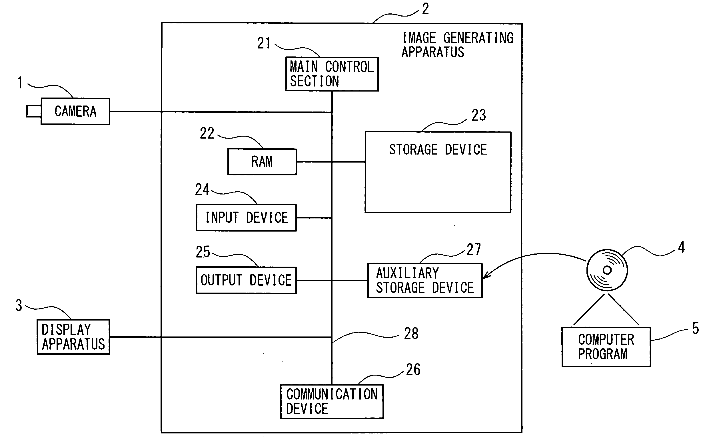
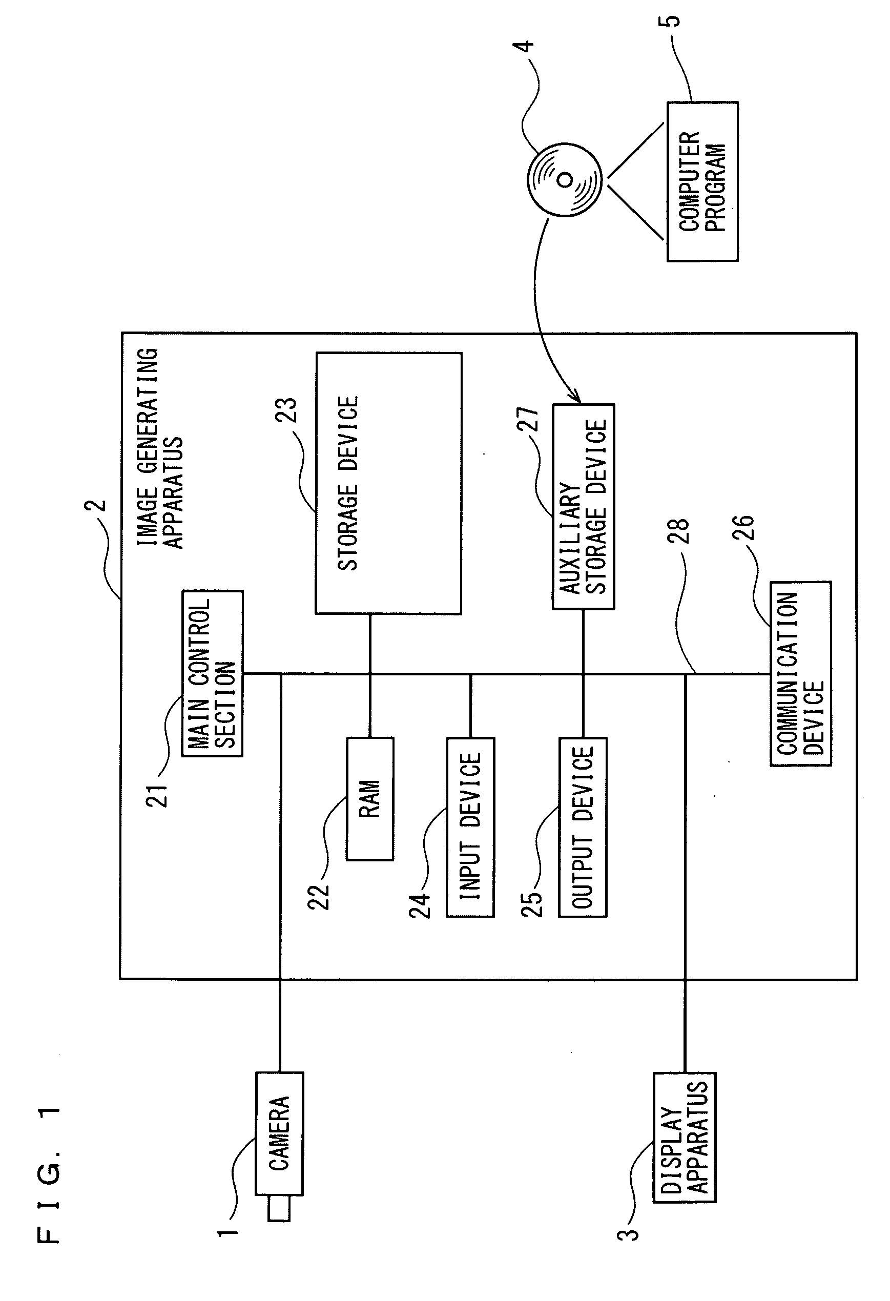
[0072]FIG. 1 is a block diagram schematically showing a configuration of an image generating apparatus according to a first embodiment of the present invention. As shown in FIG. 1, an image generating apparatus 2 according to the first embodiment is connected with a camera 1 as an image pickup device for picking up a multi-valued image, and a display apparatus 3 which displays a picked-up multi-valued image or a generated image.

[0073]The image generating apparatus 2 is configured of at least a CPU (Central Processing Unit), a main control section 21 made up of an LSI or the like, an RAM 22, a storage device 23, an input device 24, an output device 25, a communication device 26, an auxiliary storage device 27, and an internal bus 28 for connecting the foregoing hardware. The main control section 21 is connected to each hardware section as described above of the image generating apparatus 2 through the internal bus 28, and controls the operation of each of the foregoing hardware secti...

second embodiment

[0135]Since a configuration of the image generating apparatus 2 according to a second embodiment of the present invention is similar to the first embodiment, the same reference numerals are provided thereto and the specific descriptions thereof are not given. The second embodiment is different from the first embodiment in that a synthesizing rate of an original multi-valued image and a smoothing-processed image is calculated based upon an edge strength calculated in accordance with a degree of fluctuation in luminance value in a reduced image having been reduced, to generate an image with a noise portion deleted.

[0136]FIG. 12 is a flowchart showing a procedure for processing of the main control section 21 of the image generating apparatus 2 according to the second embodiment of the present invention. As shown in FIG. 12, the main control section 21 of the image generating apparatus 2 according to the second embodiment acquires a multi-valued image picked up by the camera 1 (Step S12...

third embodiment

[0152]Since a configuration of the image generating apparatus according to a third embodiment of the present invention is similar to the first embodiment, the same reference numerals are provided thereto and the specific descriptions thereof are not given. The third embodiment is different from the first and second embodiments in that a synthesizing rate of an original multi-valued image and a smoothing-processed image is calculated based upon dispersion of luminance values in a prescribed region in a reduced image having been reduced, to generate an image with a noise portion deleted.

[0153]FIG. 13 is a flowchart showing a procedure for processing of the main control section 21 of the image generating apparatus 2 according to the third embodiment of the present invention. As shown in FIG. 13, the main control section 21 of the image generating apparatus 2 according to the third embodiment acquires a multi-valued image picked up by the camera 1 (Step S1301), and generates a reduced i...


PUM


Abstract

There are provided an image generating apparatus and an image generating method, which are capable of generating an image with only a noise portion reliably deleted. A reduced image is generated by reducing the multi-valued image, smoothing processing is executed on the reduced image, an edge image is generated from the reduced image, edge angle information concerning edge angles is generated in pixel units from the edge image, a synthesizing rate of the multi-valued image and the smoothed reduced image is calculated in pixel units of the reduced image based upon the edge angle information. An enlarged image is generated by enlarging the smoothed reduced image to an identical scale, the synthesizing rate calculated in pixel units of the reduced image is converted into a synthesizing rate in pixel units of the enlarged image, and the multi-valued image and the enlarged image are synthesized based upon the converted synthesizing rate.

Description

CROSS-REFERENCE TO RELATED APPLICATIONS[0001]The present application claims foreign priority based on Japanese Patent Application No. 2008-036795, filed Feb. 19, 2008, the contents of which is incorporated herein by reference.BACKGROUND OF THE INVENTION[0002]1. Field of the Invention[0003]The present invention relates to an image generating apparatus and an image generating method, which are capable of removing an unnecessary noise portion from a multi-valued image to generate an image with a necessary edge portion left therein.[0004]2. Description of the Related Art[0005]Conventionally, when an image includes a noise portion other than an edge portion, in a case of extracting edge information from this image to perform image processing, the influence of the noise portion is inevitable. In the case of executing image matching processing through use of edge information on an image including a noise portion to a large degree, for example, there has been problems in that the matching p...

Claims


Application Information

Patent Timeline
Patent Type & Authority Applications(United States)
IPC IPC(8): G06K9/40
CPCG06T2207/20192G06T5/002G06T3/40G06T2200/24G06T2207/20012G06T5/20
Inventor SHIMODAIRA, MASATO
Owner KEYENCE
Why Eureka
Try Eureka