
Method and module for improving image fidelity

a digital image and image fidelity technology, applied in image enhancement, instruments, computing, etc., can solve the problems of low image fidelity, low image fidelity, and low image fidelity, so as to improve image fidelity, reduce spatial resolution of images, and improve image fidelity

Inactive Publication Date: 2011-04-21
UNIV DE MONTREAL
View PDF9 Cites 13 Cited by
  • Summary
  • Abstract
  • Description
  • Claims
  • Application Information

AI Technical Summary

Benefits of technology

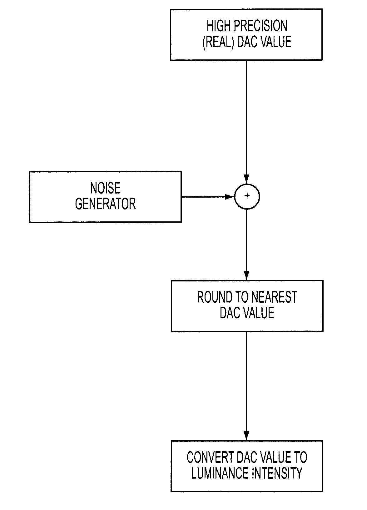
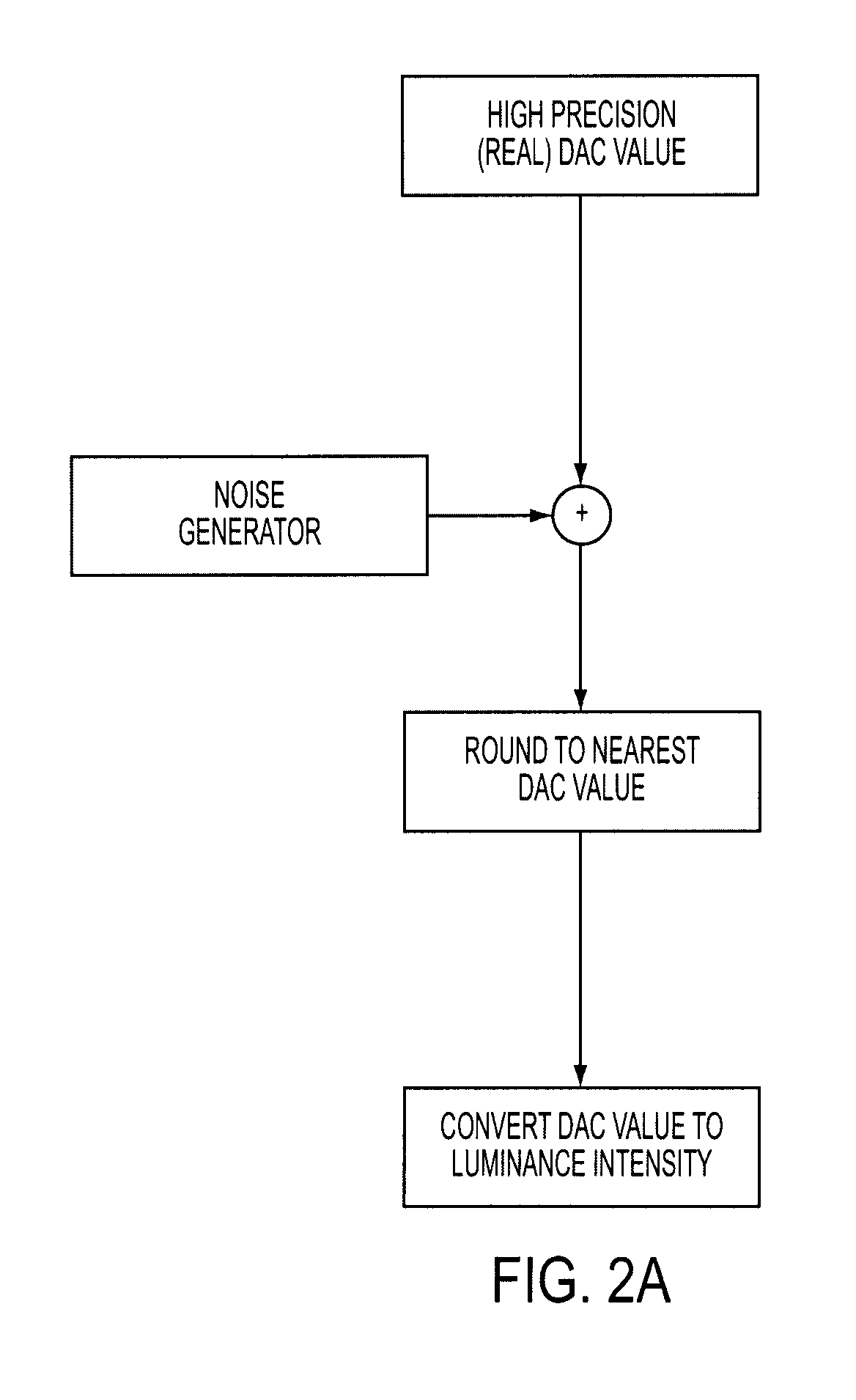
[0017]The present invention provides a method and a module for improving digital image fidelity by introducing noise to a Digital to Analog Converter value of some of the pixels.
[0018]In accordance with another aspect, the present invention relates to a module for introducing noise to a Digital to Analog Converter value of some of the pixels, integrated in one of the following: a new piece of hardware, a software, a graphic card, a television, a mobile phone display, a display for an apparatus, a digital camera display, a module for reducing spatial resolution of images, or any other type of digital displays or modules improving image fidelity.

Problems solved by technology

With ever increasing spatial resolution, temporal resolution becomes an issue.
However, this realism and precision comes at a high price, both financially and environmentally.
Although this “soft” approach has proven to be useful in improving luminance resolution, its implementation is relatively complex and does not achieve a perceptually continuous image.
Although this algorithm has the advantage of being simple to implement, the fidelity of the displayed image is not appropriate for practical use.
However, their implementation is rather complex and requires additional computer resources.
This combined method is rather complex, and its implementation impractical.
There is thus no simple solution for improving image fidelity of a digital display, and for providing digital displays with greater image fidelity.

Method used


Image

  • Method and module for improving image fidelity
  • Method and module for improving image fidelity
  • Method and module for improving image fidelity

Examples


experiment # 1

Experiment #1

[0056]Two observers participated in the study. One of them was aware of the purpose of the experiment and one of the inventors, and the other was naïve to the purpose of the experiment. Both had normal or corrected-to-normal vision.

[0057]The stimuli were presented on a 19 in ViewSonic E90FB .25 CRT monitor powered by a Pentium 4 computer combined with a Matrox Parhelia512 graphic card. All three-color guns were constrained to have the same DAC value. As a result, this setup could display 256 different luminance intensities (8-bit luminance depth). The greatest luminance intensity attainable was 94 cd / m2. The display was gamma corrected using a Minolta CS100 photometer interfaced with a homemade program to produce a linear relationship between the DAC value and the luminance intensity. The refresh rate was set to 60 Hz, which is typically the lowest refresh rate for most computers. The screen resolution was set to the most standard screen resolution of 1024×768 pixels co...

experiment # 2

Experiment #2

[0069]The previous experiment showed that the noise introduced by the noisy-bit method did not significantly affect the contrast threshold of a given task. However, this does not imply that the noise was not detectable. A given noise contrast could be perceived without affecting contrast threshold. This would result into a qualitative difference between a continuous grayscale display and discrete grayscale display combined with the noisy-bit method. The objective of the second experiment was to show that the noise introduced by the noisy-bit method was not perceived even for relatively low spatiotemporal screen resolutions. If the noise is not perceptible, not only would the noisy-bit method enable contrast threshold measurements equivalent to continuous displays, it would also be qualitatively (or perceptively) equivalent. Indeed, the difference between a continuous display and 256 grayscale display would not be measurable nor perceptible.

[0070]The same apparatus was u...


PUM


Abstract

The present invention relates to a method and a module for improving image fidelity. For doing so, the present invention introduces noise (N) to at least one DAC value of at least some pixels, using one or multiple various patterns.

Description

FIELD OF THE INVENTION[0001]The present invention relates to digital image fidelity, and more particularly to a method and module for improving image fidelity.BACKGROUND OF THE INVENTION[0002]With the advent of virtual reality, gaming, High Definition Video, digital cameras and highly sensitive measurement apparatuses, the need for high definition displays has been consistently increasing. The trend in the industry has been mostly in changing televisions and monitors for newer models with higher number of pixels and / or higher number of bits.[0003]The quality of a display is usually defined by the following criteria: spatial resolution, bit depth, contrast ratio, and temporal resolution.[0004]Spatial resolution refers to the number of individual dots of color, known as pixels, contained in a display. Spatial resolution is generally represented using a number of horizontal pixels and a number of vertical pixels. Spatial resolution varies greatly, and more recent technologies are aimin...

Claims


Application Information

Patent Timeline
Patent Type & Authority Applications(United States)
IPC IPC(8): G06K9/40
CPCG09G3/2048G06T5/002G09G2310/027G06T5/70
Inventor FAUBERT, JOCELYNALLARD, REMY
Owner UNIV DE MONTREAL
Learn More