Manual switch for a closed suction tube

a man-made switch and suction tube technology, applied in the field of switches, can solve the problems of troublesome operation, inability to achieve sealing effect, laborious operation of conventional switches, etc., and achieve the effect of excellent sealing effect and convenient operation

Inactive Publication Date: 2012-09-20
CHANG TI LI
View PDF6 Cites 5 Cited by
  • Summary
  • Abstract
  • Description
  • Claims
  • Application Information

AI Technical Summary

Benefits of technology

[0007]The main objective of the invention is to provide a manual switch for a clo

Problems solved by technology

Therefore, the operation of the conventional switch is laborious.
Otherwise, a sealing effect cannot be achieved.
Furthermore, although some conventional manual switch may furthe

Method used


Image

  • Manual switch for a closed suction tube
  • Manual switch for a closed suction tube
  • Manual switch for a closed suction tube

Examples


Embodiment Construction

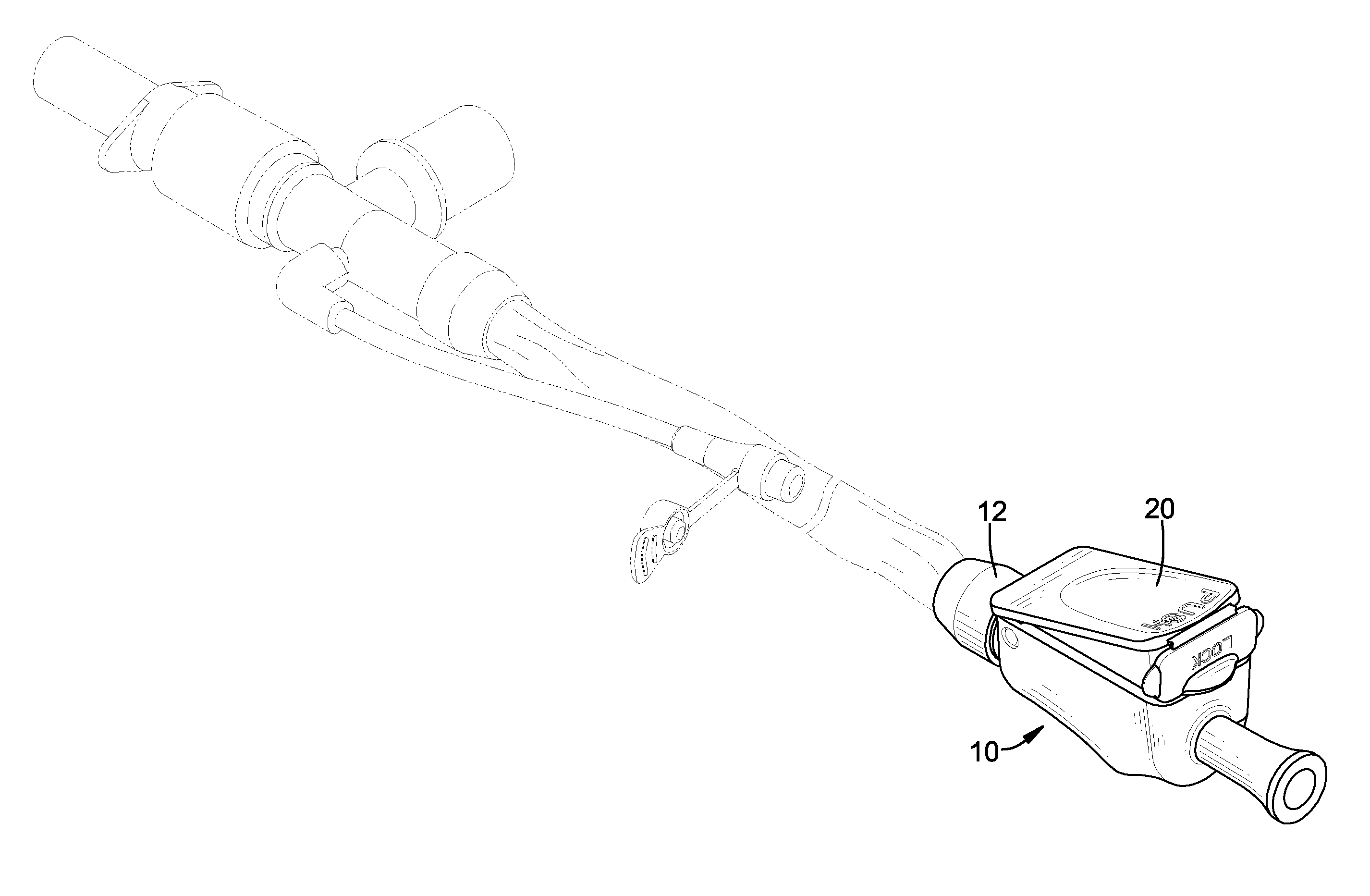
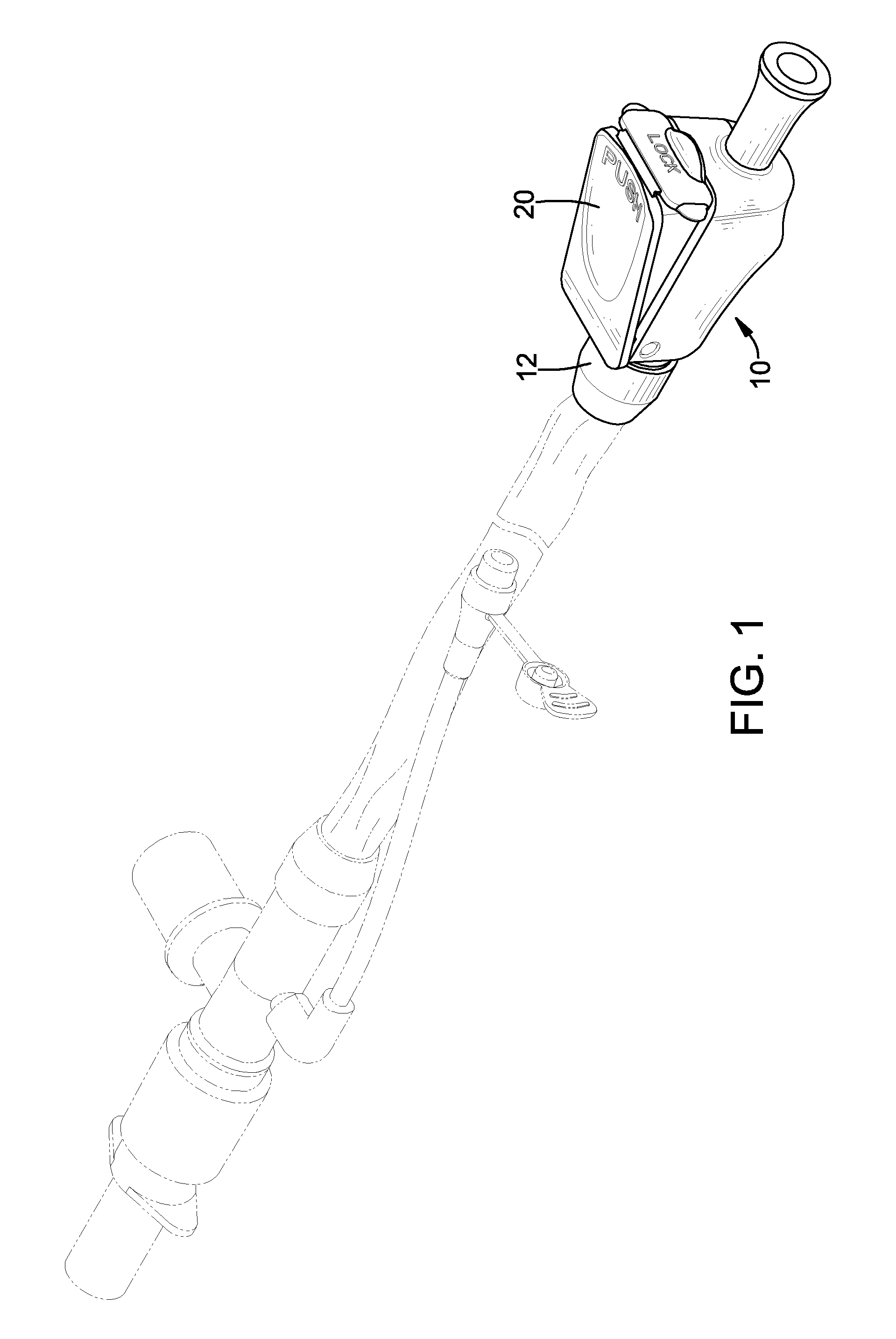
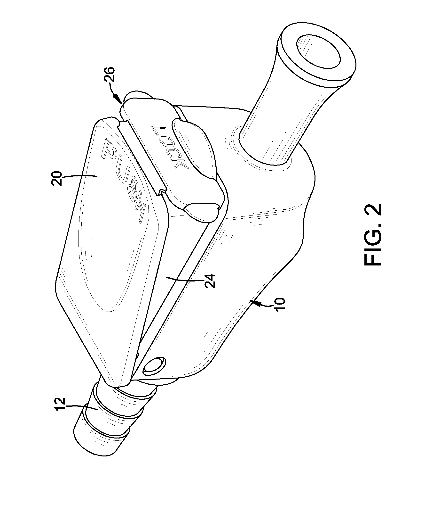
[0019]With reference to FIGS. 1 to 4, a manual switch in accordance with the present invention is connected to a closed suction tube and comprises a body 10, a button 20, a valve rod 30 and a biasing member 40. The body 10 is hollow and has two ends, a connecting tube 12 and a valve mount 14. The connecting tube 12 is mounted through the body 10 and has two ends protruding respectively from the ends of the body 10. The ends of the connecting tube 12 are connected respectively to a suction tube and a vacuum pump / compressor. The valve mount 14 is hollow, is formed in the body 10, communicates with the connecting tube 12 and has an inner diameter, an inner surface and multiple holding ribs 144. The holding ribs 144 are formed around the inner surface, are arranged in a circle and are spaced from each other to define multiple gaps 146 between the holding ribs 144.

[0020]The button 20 is connected pivotally to the body 10 at a pivotal position on the body 10. The pivotal position of the b...


PUM


Abstract

A manual switch has a body, a button, a valve rod and a biasing member. The body has a valve mount having multiple holding ribs. The valve rod is mounted slidably in the valve mount, is pressed by the button and has a valve rod, a mounting tube and an O-ring. The rod body has an outer diameter smaller than the inner diameter of the valve mount. The mounting tube is mounted securely around the rod body and has an outer diameter being equal to the inner diameter of the valve mount and an outer surface abutting with the holding ribs in the valve mount. The O-ring is mounted around the rod body and abuts with the inner surface of the valve mount to provide a sealing effect to the valve rod and the valve mount.

Description

BACKGROUND OF THE INVENTION[0001]1. Field of the Invention[0002]The present invention relates to a switch, and more particularly to a manual switch for a closed suction tube for drawing secretion out from a human body and having an excellent sealing effect and a labor-saving capability.[0003]2. Description of Related Art[0004]A manual switch is mounted on a closed suction tube to manually control the suction tube to draw secretion out from a patient. With reference to FIG. 9, a conventional manual switch is connected to the suction tube and a vacuum pump / compressor and has a body 60, a button 62, a valve rod 64 and a spring 66. The body 60 has a connecting tube with two ends connected respectively with the suction tube and vacuum pump / compressor. The button 62 is mounted slidably on the body 60. The valve rod 64 is movable mounted in the body 60, is released upward by the button 62 and is mounted into the connecting tube to close the communication of the connecting tube. The spring ...

Claims


Application Information

Patent Timeline
IPC IPC(8): A61M5/00
CPCA61M39/284A61M39/28
Inventor CHANG, TI-LI
Owner CHANG TI LI
Why Eureka
Try Eureka