Speed change controlling apparatus for motorcycle

Active Publication Date: 2012-09-20
HONDA MOTOR CO LTD
View PDF1 Cites 21 Cited by
  • Summary
  • Abstract
  • Description
  • Claims
  • Application Information

AI Technical Summary

Benefits of technology

[0013]According to this aspect of the invention, since the control section changes the switching speed of a clutch of the twin clutch type speed change gear which includes a one-side clutch and the other side clutch to make the magnitudes of the driving force variation in the soft speed change control, normal speed change control and direct speed change control different from one another, setting of the magnitude of the driving force variation in each speed change control can be executed easily and accurately.
[0014]In further accordance with the present invention, as the roll angle increases, the timing at which the clutch capacity is to be increased is delayed in order to change over the one side clutch or the other side clutch which has been in a disconnection state before the speed change into a connection state. As the roll angle increases, the timing at which the clutch capacity is to be increased is delayed in order to change over the one side clutch or the other side clutch which has been in a disconnection state before the speed change into a connection state. Therefore, adjustment of the clutch switching speed can be executed readily by control of the clutch capacity.
[0015]Further, the roll angle is decided with reference to a gravity direction using the roll angle detection device which is configured from a gyro sensor. Since the roll angle is decided with reference to the gravity direction using the roll angle detection device configured from a gyro sensor, an accurate roll angle can be obtained without being influenced by an inclination angle of the road surface or the like.
[0016]In accordance with another aspect of the invention, when the roll angle exceeds the second roll angle, the speed change operation is inhibited. T

Problems solved by technology

Where control only of inhibiting speed change operation is carried out with reference to a single predetermined angle as in such a technique as disclosed in J

Method used


Image

  • Speed change controlling apparatus for motorcycle
  • Speed change controlling apparatus for motorcycle
  • Speed change controlling apparatus for motorcycle

Examples


Embodiment Construction

[0036]In the following, a preferred embodiment of the present invention is described in detail with reference to the drawings. Unless otherwise specified, directions such as forward, backward, leftward and rightward directions in the description given below are same as those of a vehicle. Further, an arrow mark FR in the drawings indicates the forward direction of the vehicle, an arrow mark LH indicates the leftward direction of the vehicle, and an arrow mark UP indicates the upward direction of the vehicle.

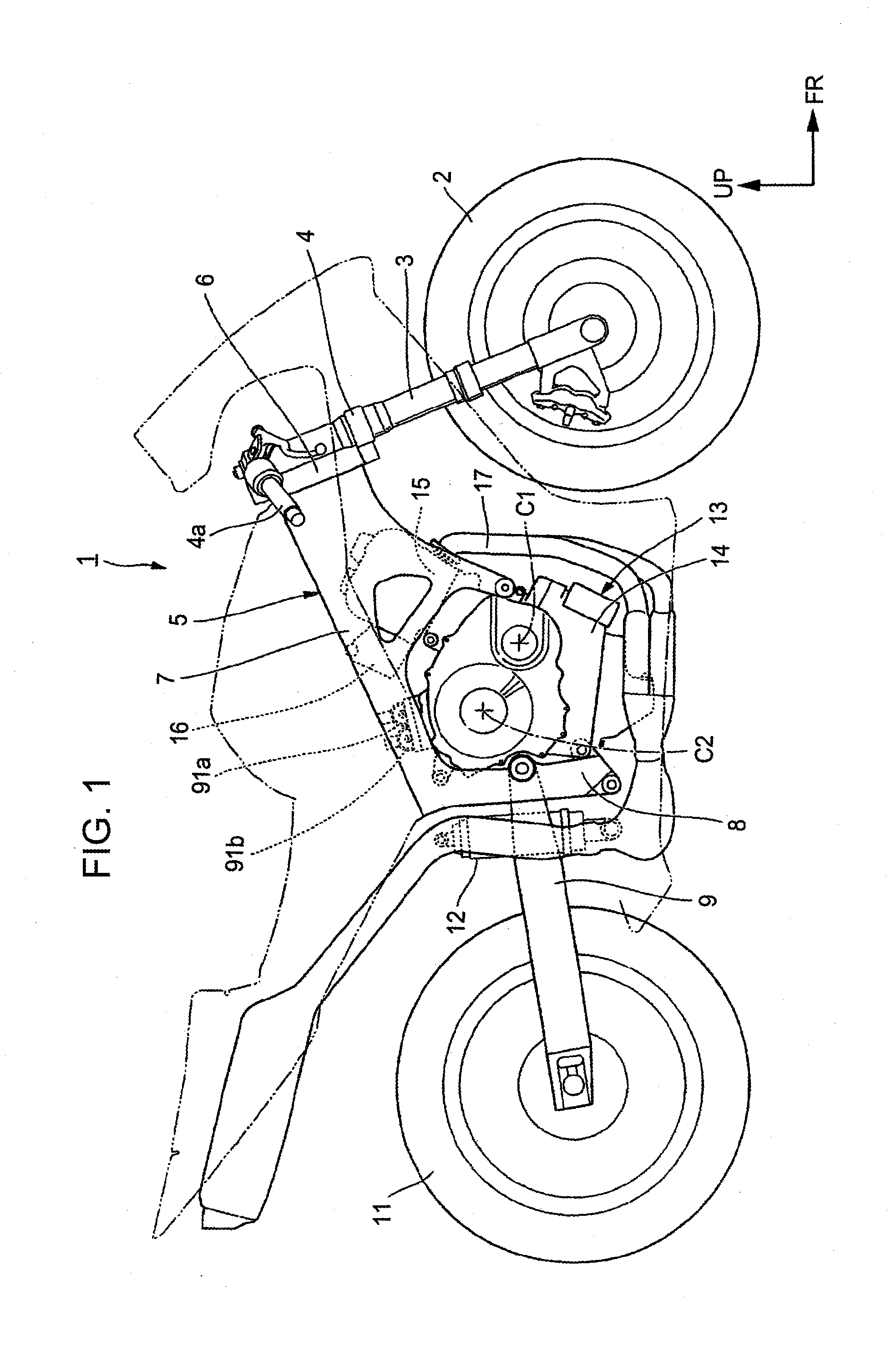
[0037]FIG. 1 is a side elevational view of a motorcycle 1 as a saddle type vehicle to which a speed change controlling apparatus according to the present embodiment is applied. A front fork 3 which supports a front wheel 2 for rotation thereon is pivotally supported at an upper portion thereof on a head pipe 6 at a front end portion of a vehicle body frame 5 through a steering stem 4 for steering manipulation. A steering handle bar 4a is mounted at an upper portion of the steerin...


PUM


Abstract

A speed change controlling apparatus in which the mode of driving force transmission is depends upon the roll angle of a vehicle body. When a roll angle is within a range from a second roll angle, which corresponds to a full bank state, to a first roll angle, speed change operation is carried out by soft speed change control in which variation of the driving force with respect to time is smaller than that by normal speed change control. If the roll angle is within another range from the first roll angle to a third roll angle, then normal speed change is carried out and if the roll angle is within a further range from an uprightly standing state to the third roll angle, then speed change operation is executed by direct speed change. When the roll angle is greater than the second roll angle, speed change is inhibited.

Description

BACKGROUND OF THE INVENTION[0001]1. Field of the Invention[0002]The present invention relates to a speed change controlling apparatus for a motorcycle, and particularly to a speed change controlling apparatus for a motorcycle capable of executing speed change control in response to a roll angle of a vehicle body.[0003]2. Description of Related Art[0004]Conventionally, an automatic transmission is known which changes over meshing engagement of speed change gears by an actuator such as a motor so that the speed can be changed automatically (full-automatic) or semi-automatically (semi-automatic). Such an automatic transmission as just described automatically changes the speed based on information of an engine speed, a shift stage of the transmission, a throttle opening and so forth upon full-automatic speed change but carries out speed change operation in response to an operation of a speed changing switch mounted on a steering handle bar or the like upon semi-automatic speed change.[0...

Claims


Application Information

Patent Timeline
IPC IPC(8): B60W10/02B60W10/10F16H61/00
CPCB60Y2300/022F16H61/16B60Y2200/12F16H61/0437B60W2520/18B60W30/02B60W30/18145B60W2520/14B60W10/113
Inventor KOJIMA, HIROYUKINAKAGAWARA, MASAKIOZEKI, TAKASHITSUKADA, YOSHIAKI
Owner HONDA MOTOR CO LTD
Why Eureka
Try Eureka