Control Device And Robot System

a control device and robot technology, applied in the field of robot system and robot technology, can solve the problems of the inability to measure the effect of all the combinations of all the attitudes and the masses of all the work pieces in which vibration is a problem, and the inability to accurately apply the impa

Active Publication Date: 2018-10-04
SEIKO EPSON CORP
View PDF0 Cites 5 Cited by
  • Summary
  • Abstract
  • Description
  • Claims
  • Application Information

AI Technical Summary

Benefits of technology

[0009]An advantage of some aspect of the invention is to solve at least a part of the problems described above, and the invention can be implemented as the following forms or application examples.

Problems solved by technology

As a result, eigenfrequencies in combinations of all the attitudes and the masses of all the work pieces in which vibration is a problematic may not be measured.
However, depending on an environment in which the robot is installed, a space in the periphery of the robot is small and an impact may not be applied to the robot with a hammer.
That is, there is a possibility of an impact not being applied accurately depending on a problematic vibration direction.
Further, when delivery and setting of a robot are executed, a client which is a delivery destination of the robot may not want a deliverer of the robot to apply an impact to the robot with a hammer.

Method used


Image

  • Control Device And Robot System
  • Control Device And Robot System
  • Control Device And Robot System

Examples


modification examples

D. Modification Examples

D1. Modification Example 1

[0302](1) In the foregoing embodiment, there are the plurality of third control signals output between the earlier and later control signals (see FIGS. 6 and 8). However, only one third control signal may be output between an output of the earlier control signal and an output of the later control signal.

[0303](2) In the foregoing embodiment, there are the plurality of second control signals generated by reducing different frequency components (see numbers 1 to 15 of FIG. 3). However, an aspect in which only one second control signal in which the frequency component is reduced can be generated and applied can also be set.

[0304](3) In the foregoing embodiment, the third control signal can be obtained as a weighted mean of the earlier and later control signals. However, the third control signal can be determined also considering a component other than the earlier and later control signals.

[0305](4) In the foregoing embodiment, when both...

modification example 2

D2. Modification Example 2

[0314](1) In the foregoing embodiment, when the first condition including non-input of the instruction indicating execution of the reduction in the frequency component is satisfied, the first control signal in which the frequency component is not reduced is output by the filter processing unit 340. The first condition can further include another condition such as a condition that predetermined setting is executed or a condition that the predetermined setting is not executed as an inferior weighted condition.

[0315]As the inferior weighted condition, for example, (a) a condition that an instruction not indicating the reduction in the frequency component is input can be exemplified. As the inferior weighted condition, (b) a condition that a password determined in advance is input (c) a condition that an ID determined in advance and a password corresponding to the ID are input, and (d) a condition that the instruction of (a) is input via hardware (see reference...

modification example 3

D3. Modification Example 3

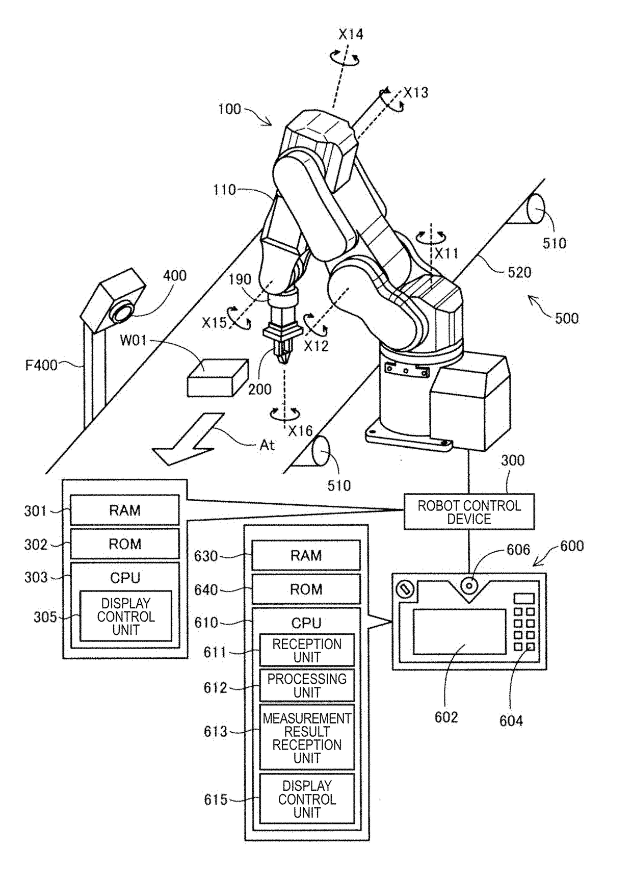
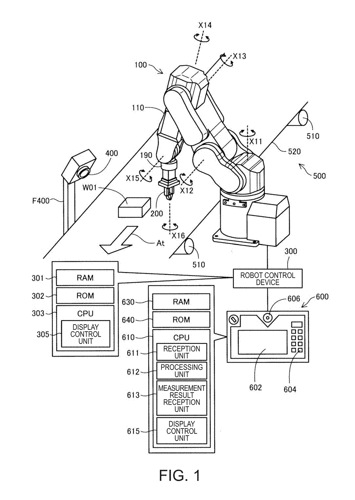
[0326](1) In the present specification, the description of “the measurement unit installed in the robot” include a measurement unit embedded as a part of the configuration of the robot in advance and a measurement unit installed in the robot at the time of measurement.

[0327](2) In the foregoing embodiment, the setting device 600 and the robot control device 300 can also receive an instruction indicating execution of one specific operation and can also receive an instruction indicating continuous execution of a plurality of specific operations. Then, the setting device 600 and the robot control device 300 can receive the instruction indicating execution of one specific operation at a different timing. Then, the specific operations instructed at the different timings may be the same specific operation or may be different types of specific operations. That is, the reception unit 611 serving as a reception unit can receive the instruction indicating a plurality...


PUM


Abstract

A control device includes: a processor that is configured to execute computer-executable instructions so as to control a robot, and the processor is configured to receive an instruction to execute a specific operation which is an operation determined in advance; and an amplifier that causes a motor of a robot to execute the specific operation when the processor receives the instruction to execute the specific operation; wherein the processor is configured to receive a measurement result of vibration measured by a measurement device installed in the robot from the measurement device in the execution of the specific operation.

Description

BACKGROUND1. Technical Field[0001]The present invention relates to a technology for reducing vibration in a robot.2. Related Art[0002]In the related art, in the fields of robot technologies, there are technologies for reducing vibration of work pieces held by end effectors. In the technology of JP-A-2001-293638, a vibration frequency at which a robot resonates in a state in which a work piece is held in advance by an end effector is specified. Then, a band-elimination filter is applied to a torque control signal (which can be ascertained as a time function) which is provided to a current control unit controlling driving of a servo motor of a robot to eliminate a component of the vibration frequency from the torque control signal. As a result, the torque control signal which does not include the component of the vibration frequency is provided to the current control unit. A servo motor of which the driving is controlled by the current control unit based on the torque control signal d...

Claims


Application Information

Patent Timeline
Patent Type & Authority Applications(United States)
IPC IPC(8): B25J9/16
CPCB25J9/1628Y10S901/09Y10S901/46B25J9/1697B25J9/1602B25J9/1694B25J19/00B25J9/1633G05B2219/37351G05B2219/37534G05B2219/41145G05B2219/41166G05B2219/41232
Inventor HIRAIDE, TOSHINORIYOKOSHIMA, NORIO
Owner SEIKO EPSON CORP
Why Eureka
Try Eureka