Method of fracturing a subterranean formation at optimized and pre-determined conditions

Active Publication Date: 2012-09-27
BAKER HUGHES INC
View PDF1 Cites 11 Cited by
  • Summary
  • Abstract
  • Description
  • Claims
  • Application Information

AI Technical Summary

Benefits of technology

[0019](3) characterization of the horizontal velocity within the hydraulic fracture.From such information, the propped fracture length of the treatment process may be accurately estimated.

Problems solved by technology

The most significant disadvantage associated with slickwater fracturing is poor proppant transportability afforded by the low viscosity treating fluid.
Poor proppant transport results in the tendency of proppants to settle rapidly, often below the target zone, yielding relatively short effective fracture lengths and consequently, steeper post-stimulation production declines than may be desired.
First, fracture height typically develops beyond the boundaries of the productive zone, thereby diverting portions of the transport slurry into non-productive areas.
Second, there exists a tendency for the proppant to settle during the pumping operation or prior to confinement by fracture closure following the treatment, potentially into non-productive areas.
Third, damage to the proppant pack placed within the productive zone often results from residual fluid components.
This causes decreased conductivity of the proppant pack.
Still, the mechanics of proppant transport are generally not well understood.
As a result, optimized effective fracture area is generally not attained.

Method used


Image

  • Method of fracturing a subterranean formation at optimized and pre-determined conditions
  • Method of fracturing a subterranean formation at optimized and pre-determined conditions
  • Method of fracturing a subterranean formation at optimized and pre-determined conditions

Examples


example 1

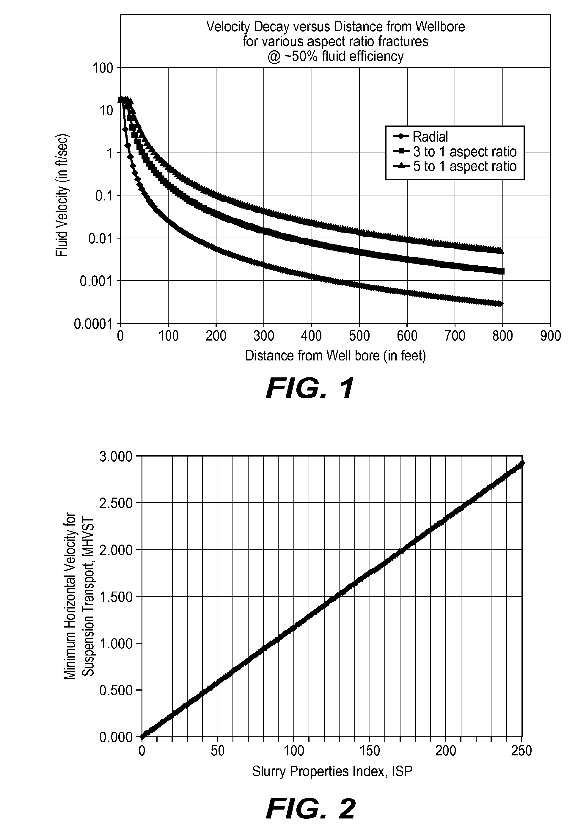
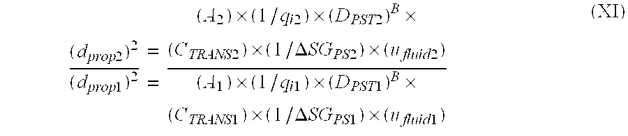
[0095]The distance a transport fluid containing a proppant comprised of 20 / 40 ULW proppant having an specific gravity of 1.08 and 29 cP slickwater would be transported in a fracture having a 3:1 length to height geometry with a 1 bpm / ft injection rate was obtained by first determining the minimum horizontal velocity, MHVST, required to transport the proppant in the slickwater:

MHVST=CTRANS×(d2prop)×(1 / μfluid)×(ΔSGPS);

or

MHVST=(1150)×(CTRANS)×(0.5810)×(1 / 29)×(1.08−1.00)=0.022 ft / sec.

The distance was then required by as follows:

DPSTB=MHVST / A

wherein A for a 3:1 length to height geometry is 5261.7 and B is −2.2412; or

DPST−2.2412=0.022 / 5261.7;

DPST=251 ft.

example 2

[0096]The distance a transport fluid containing a proppant comprised of 20 / 40 Ottawa sand and 7 cP 2% KCl brine would be transported in a fracture having a 3:1 length to height geometry with a 1 bpm / ft injection rate was obtained by first determining the minimum horizontal velocity, MHVST, required to transport proppant in the slickwater as follows: MHVST=CTRANS×(d2prop)×(1 / μfluid)×(ΔSGPS); or

MHVST=(1150)×(CTRANS)×(0.4032)×(1 / 7)×(2.65−1.01)=1.27 ft / sec

wherein the 1150 multiplier is a unit conversion factor.

The distance was then determined as follows:

DPSTB=MHVST / A

wherein A for a 3:1 length to height geometry is 5261.7 and B is −2.2412; or

DPST−2.2412=1.27 / 5261.7;

DPST=41 ft.

example 3

[0097]For a transport fluid containing a proppant having the following properties:

[0098]Proppant diameter: 0.635 mm

[0099]Specific gravity of proppant: 1.25

[0100]Fluid viscosity: 30 cP

[0101]Specific gravity of transport fluid: 1.01

the propped fracture length, DPST, for a fracture having a 3:1 length to height geometry with a 5 bpm / ft injection rate was determined as follows:

(DPST)B=(qi)×(1 / A)×(CTRANS)×1150×(d2prop)×(1 / μfluid)×(ΔSGPS)

(DPST)B=(5)×(1 / 5261.7)×(0.117)×(0.635)2×(1 / 30)×(1.25−1.01)

DPST=90.4 ft.


PUM


Abstract

During a hydraulic fracturing treatment operation, one of three operational parameters may be modified in a successive stage by adjustment of another operational parameter to attain a fracture of length DPST. The operational parameters include the proppant size, viscosity of the transport fluid and injection rate of the transport fluid.

Description

[0001]This application is a continuation-in-part application of U.S. patent application Ser. No. 13 / 243,753, filed on Sep. 23, 2011, which is a divisional application of U.S. patent application Ser. No. 12 / 688,959, now U.S. Pat. No. 8,051,911, which is a divisional application of U.S. patent application Ser. No. 11 / 706,033, now U.S. Pat. No. 7,669,655.FIELD OF THE INVENTION[0002]A method of optimizing variables affecting stimulation treatments in order to improve well productivity is disclosed.BACKGROUND OF THE INVENTION[0003]In a typical hydraulic fracturing treatment, fracturing treatment fluid comprising a transport slurry containing a solid proppant, such as sand, is injected into the wellbore at high pressures.[0004]The transport of sand, as proppant, was examined in Biot and Medlin, “Theory of Sand Transport in Thin Fluids”, SPE 14468, Sep. 22-25, 1985, which is herein incorporated by reference. In Biot-Medlin, it was determined that the mechanics of sand transport are princip...

Claims


Application Information

Patent Timeline
IPC IPC(8): E21B43/267
CPCE21B49/008E21B43/26
Inventor BRANNON, HAROLD DEAN
Owner BAKER HUGHES INC
Why Eureka
Try Eureka