Selector Switch Assembly For Load Tap Changer

a switch assembly and load technology, applied in the direction of gearing elements, mechanical equipment, hoisting equipment, etc., can solve the problems of difficult manufacturing of conventionally complex devices

Active Publication Date: 2012-09-27
HITACHI ENERGY SWITZERLAND AG
View PDF5 Cites 22 Cited by
  • Summary
  • Abstract
  • Description
  • Claims
  • Application Information

AI Technical Summary

Benefits of technology

[0007]Other objectives, features and characteristics of the present invention, as well as the methods of operation and the functions of the related elements of the structure, the combination of parts and economic

Problems solved by technology

As such, these assemblies and, load tap changers in general, are conventionally c

Method used


Image

  • Selector Switch Assembly For Load Tap Changer
  • Selector Switch Assembly For Load Tap Changer
  • Selector Switch Assembly For Load Tap Changer

Examples


Embodiment Construction

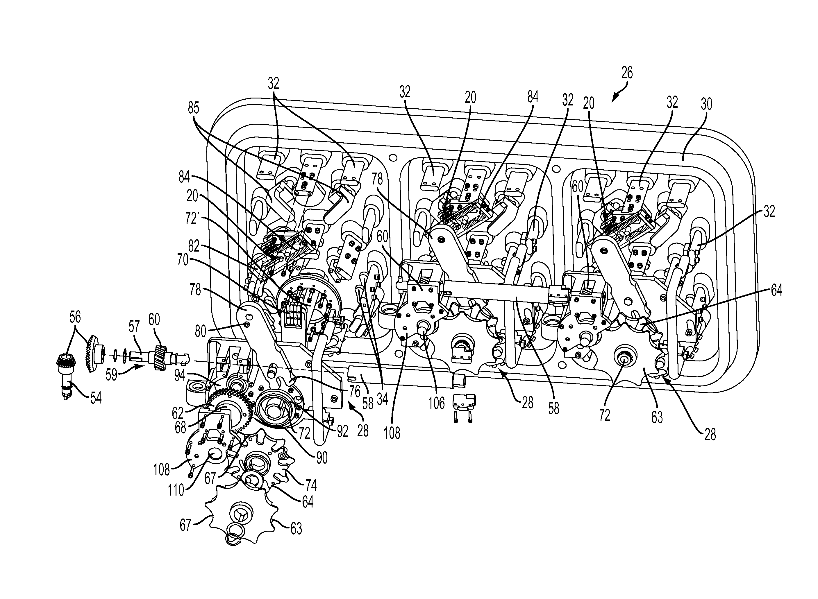
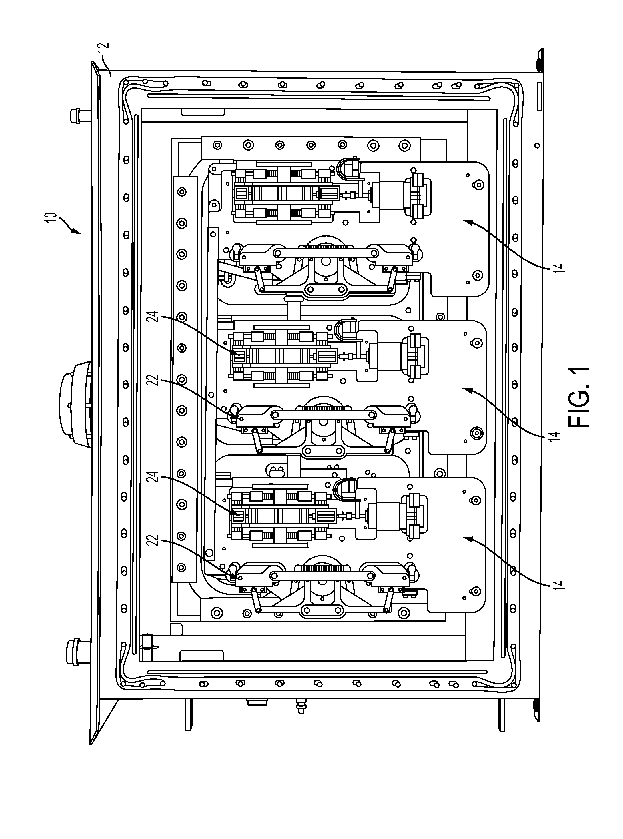
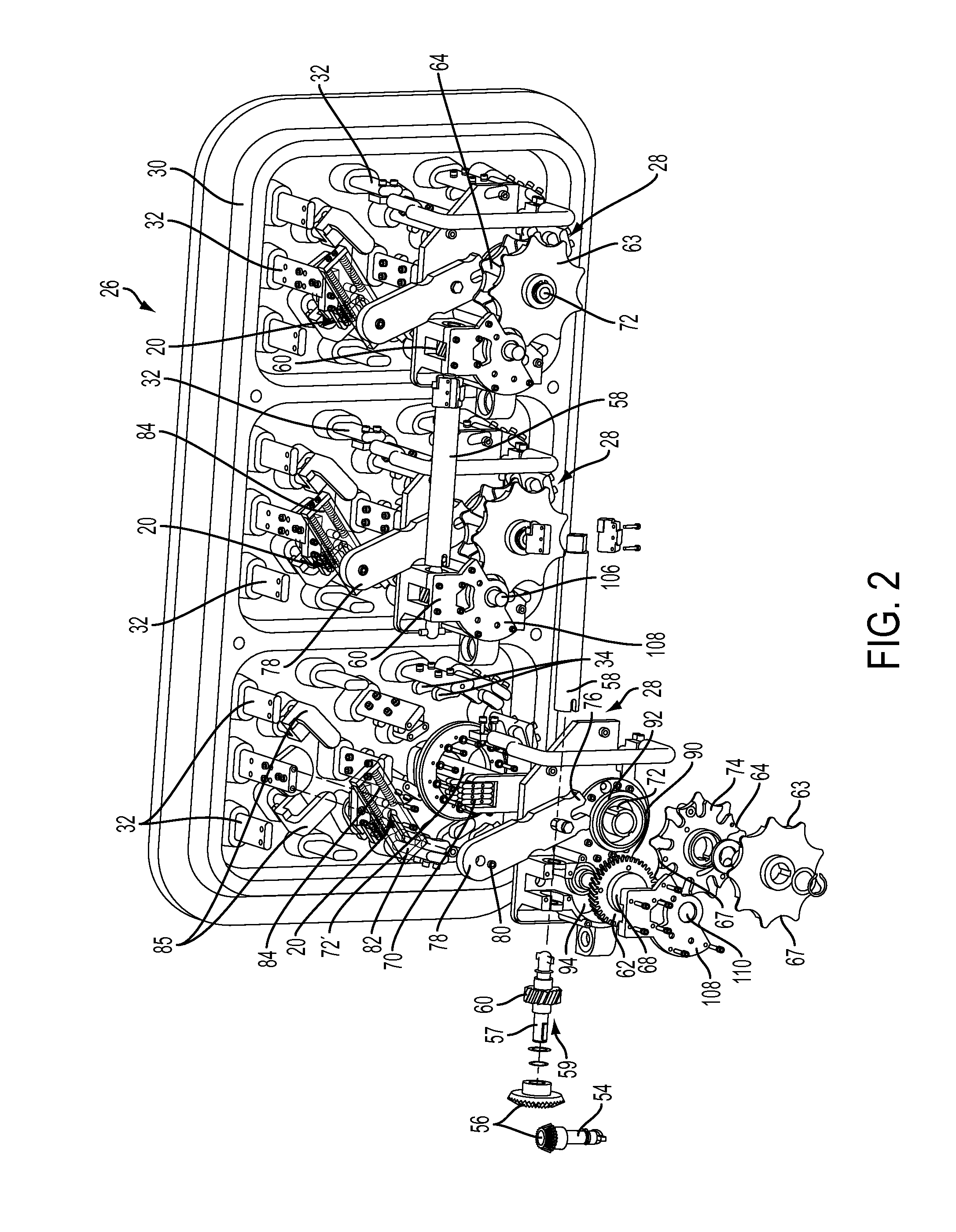
[0020]With reference to FIG. 1 a tap changing assembly is shown, generally indicated at 10, in accordance with an embodiment of the invention. The assembly 10 includes a housing 12 (shown with cover removed) that contains three circuits or diverters 14, each of which is operable to change taps on a regulating winding 16 (see FIG. 3) for one phase of a transformer. Each diverter 14 may be utilized in a linear configuration, a plus-minus configuration or a coarse-fine configuration. In the linear configuration, the voltage across the regulating winding 16 is added to the voltage across a main (low voltage) winding 18 (FIG. 3). In the plus-minus configuration, the regulating winding 16 is connected to the main winding 18 by a change-over switch 20, which permits the voltage across the regulating winding 16 to be added or subtracted from the voltage across the main winding 18. In the coarse-fine configuration, there is a coarse regulating winding (not shown) in addition to the (fine) re...


PUM


Abstract

A selector switch assembly for a load tap changer includes a bevel gear coupled with a motor drive shaft. A shaft assembly is coupled with the bevel gear and a switch is provided for each phase. Each switch includes a helical gear fixed to the shaft assembly, a Geneva pinion gear engaged with the helical gear, a first Geneva gear wheel mounted on a first shaft moved by a first follower of the pinion gear, a first contact arm associated with the first Geneva gear wheel to rotate therewith, a second Geneva gear wheel mounted on a second shaft and moved by a second follower of the pinion gear, and a second contact arm associated with the second Geneva gear wheel so as to rotate therewith. The contact arms include contacts that engage fixed contacts that define tap positions of the load tap changer.

Description

BACKGROUND OF THE INVENTION [0001]The present invention relates to load tap changers and, more particularly, to selector switch assembly for a load tap changer.[0002]As is well known, a transformer converts electricity at one voltage to electricity at another voltage, either of higher or lower value. A transformer achieves this voltage conversion using a primary winding and a secondary winding, each of which are wound on a ferromagnetic core and comprises a number of turns of an electrical conductor. The primary winding is connected to a source of voltage and the secondary winding is connected to a load. Voltage present on the primary winding is induced on the secondary winding by a magnetic flux passing through the core. The voltages induced on each turn of the secondary winding are cumulative and therefore the voltage output from the secondary winding is proportional to the strength of the magnetic flux and the number of turns in the secondary winding. Since the amount of magnetic...

Claims


Application Information

Patent Timeline
IPC IPC(8): H01H19/02F16H55/17
CPCH01H9/0011Y10T74/19879H01H3/44
Inventor BRASHER, JON C.GEIBEL, DAVID M.TEISING, WILLIAM J.ELICK, ROBERT A.THURMOND, JR., BOBBY OWEN
Owner HITACHI ENERGY SWITZERLAND AG
Why Eureka
Try Eureka