
External material clamp and external material clamping structure

a technology of external material and clamping structure, which is applied in the direction of washstands, scaffold accessories, lighting support devices, etc., can solve the problems of large external material load and external material deformation, and achieve the effects of preventing excess load, preventing external material breakage and deformation, and preventing excess load

Active Publication Date: 2012-09-27
KMEW CO LTD
View PDF17 Cites 29 Cited by
  • Summary
  • Abstract
  • Description
  • Claims
  • Application Information

AI Technical Summary

Benefits of technology

[0028]This invention discloses the external material clamp which comprises a receiving plate. At least a part of the receiving plate is located above the horizontal plate. Therefore, a part of the load of the external material in the upper side is supported by the receiving plate. Consequently, it is possible to fix a plurality of the external materials with prevention of applying the excess load to the external material in the lower side. Therefore, even if the large load is caused by fixing and arranging a plurality of the external materials in the vertical direction, it is possible to prevent the breakage and the deformation of the external material. That is, the load of the external material in the upper side is shared by “the external material in the lower side” and “the receiving plate of the external material clamp”. Therefore, applying the excess load to the external material in the lower side is prevented. Further, the receiving plate receives a part of the load of the external material. Therefore, there is no possibility that only the receiving plate receives the excess load. So, it is possible to damage the foundation of the wall. Consequently, applying the excess load to the external material as well as applying the load to the foundation of the wall is prevented. Therefore, it is possible to prevent the breakage and the deformation of the external material.
[0029]Furthermore, the receiving plate is realized by the receiving support plate which is formed by cutting out the upper support plate. Therefore, additional work is not required, compared with a case where the receiving plate is formed by the separate components. Therefore, it is possible to easily form the receiving plate.
[0030]In addition, the receiving plate is realized by the receiving horizontal plate which is formed by cutting out a horizontal plate. Consequently, there is no need to perform additional work if the receiving plate is formed by the separate components. Therefore, it is possible to easily form the receiving plate.
[0031]In addition, the receiving plate is realized by the receiving fixed plate which is formed by cutting out a part of the fixed plate. Consequently, there is no need to perform additional work if the receiving plate is formed by the separate components. Therefore, it is possible to easily form the receiving plate.
[0032]In addition, the lower support plate is provided with the fixing support plate projected to the fixed plate from the lower support plate. Therefore, an upper end portion of the external material in the lower side is held and fixed between the fixing support plate and the fixed plate. Therefore, it is possible to support the external material with reducing the backlash.
[0033]Furthermore, the structure uses the external material clamp with the receiving plate. A load of the external material in the upper side is shared by “the receiving plate of the external material clamp” and “The external material in the lower side”. Therefore, it is possible to prevent the excess load from being applied to the external material. Furthermore, the receiving plate receives a part of the load of the external material. Therefore, there is no possibility that the excess load is applied to only the receiving plate, whereby there is no possibility of damaging the foundation of the wall. Therefore, it is possible to prevent both “the applying the load to the foundation of the wall” and “applying excess load to the receiving plate”. Therefore, it is possible to prevent the breakage and the deformation of the external material.

Problems solved by technology

However, in the external material clamping structure, there is a possibility of applying large load to the external material 50 of the lower side.
Applying the large load to the exterior wall 50 causes the problem such as the breakage and the deformation of the external material 50.

Method used


Image

  • External material clamp and external material clamping structure
  • External material clamp and external material clamping structure
  • External material clamp and external material clamping structure

Examples


Embodiment Construction

[0069]Hereinafter, the embodiments of this invention are explained.

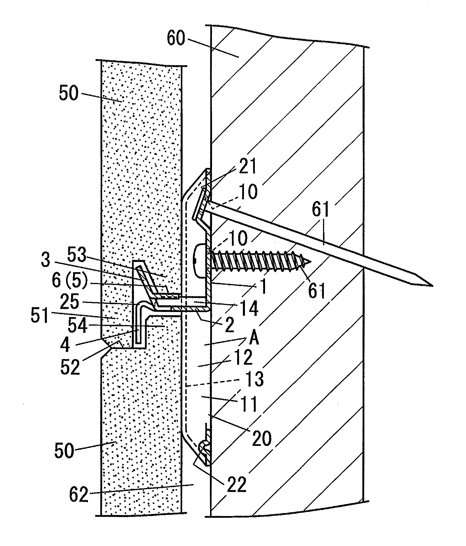
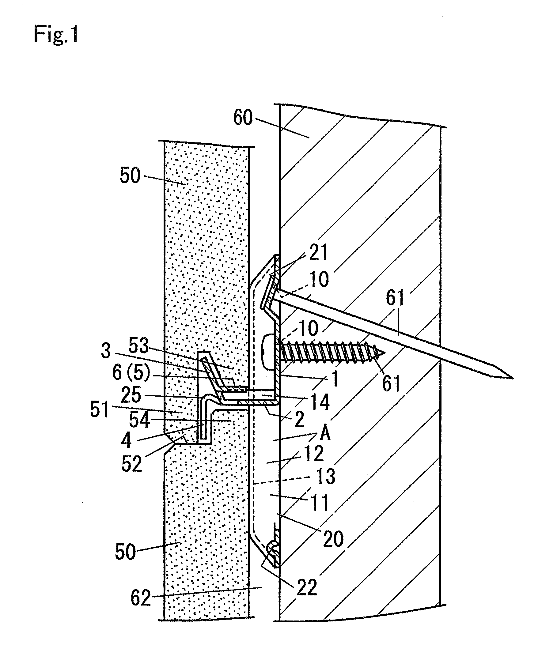
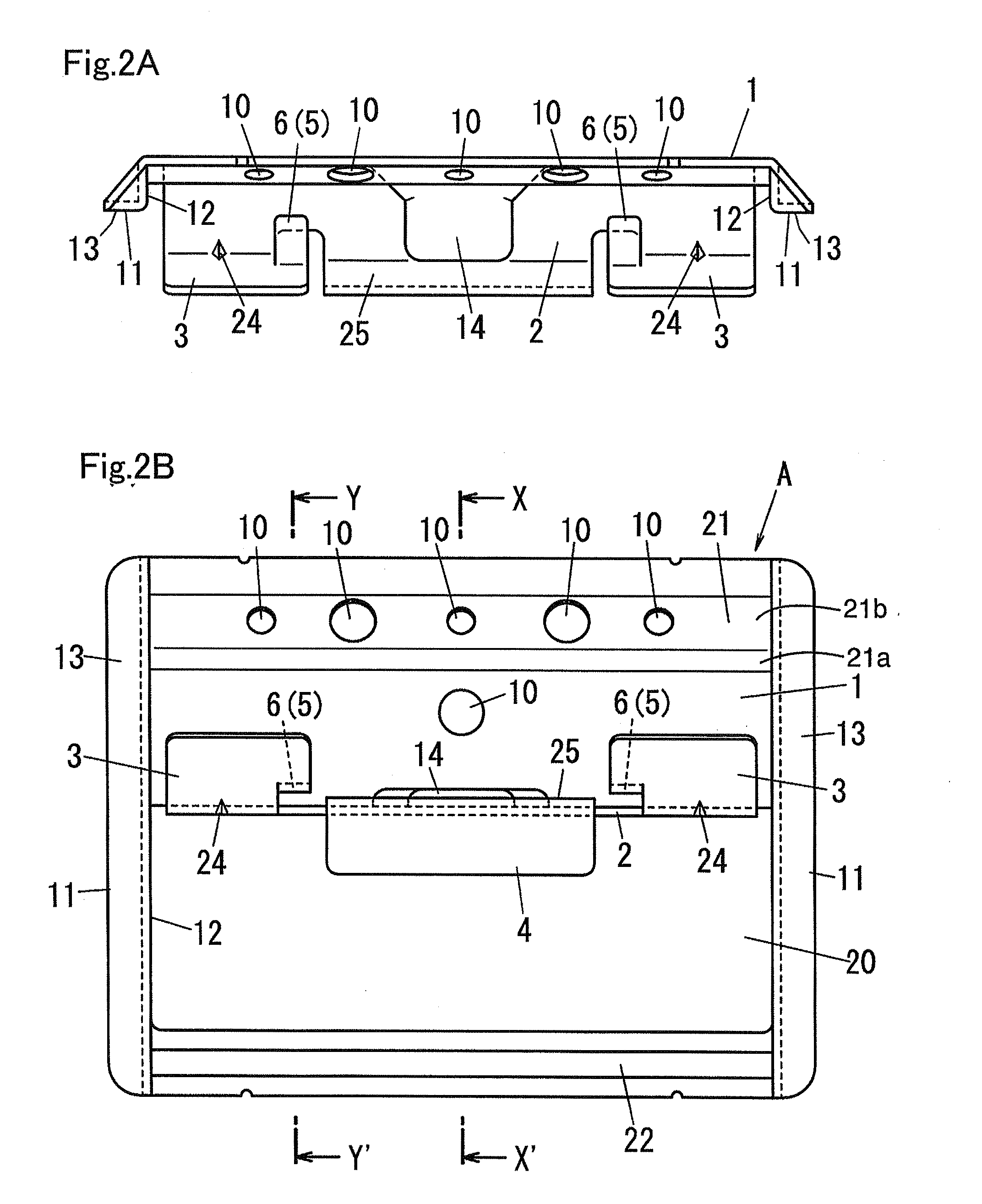
[0070]FIG. 2 and FIG. 3 each show one embodiment of the external material clamp A. FIG. 1 shows the external material clamping structure indicating the external material 50 fixed to the foundation 60 of the wall with the external material clamp A.

[0071]The external material clamp A comprises the fixed plate 1, the horizontal plate 2, the upper support plate 3, and the lower support plate 4. The horizontal plate 2 extends to a front direction from a center of the fixed plate 1. The upper support plate 3 extends to the upper direction from the front end of the horizontal plate 2. The lower support plate 4 extends to the lower direction from the front end of the horizontal plate 2. The external material clamp A is manufactured by way of, for example, “cutting the metal plate” and “bending the metal plate”, arbitrarily. In the illustrated embodiment, the horizontal plate 2, the upper plate 3, and the lower plate 4 are fo...


PUM


Abstract

The external material clamp comprises the fixed plate fixed to the foundation of the wall of the building, the horizontal plate extending forwardly from the center of the fixed plate, the upper support plate projected upwardly from the front end of the horizontal plate to support the upper side external wall with engagement, the lower support plate supporting the upper end of the external material 50 in the lower side with engagement, and the receiving plate at least a part of which is located above the horizontal plate to contact with the external material in the upper side with receiving a part of the load thereof. With this configuration, the load of the upper side external material is shared by the lower side external material and the receiving plate of the external material clamp.

Description

TECHNICAL FIELD[0001]This invention relates to an external material clamp which is used for fixing the external material to a foundation of the wall of the building. In addition, this invention relates to an external material clamping structure for fixing the external materials to the foundation of the wall of the building with the external material clamp.BACKGROUND ART[0002]FIG. 12 shows the conventional external material clamping structure for fixing the external material 50 to the foundation 60 of the wall of the building with the external material clamp A. (Refer to Patent Literature 1 hereinafter explained) The external material clamp A comprises a fixed plate 1, a horizontal plate 2, an upper support plate 3, and a lower support plate 4. The horizontal plate 2 extends to a front direction from a center of the fixed plate 1. The upper support plate extends to an upper direction from a front end of the horizontal plate 2. The lower support plate 4 extends to the lower direction ...

Claims


Application Information

Patent Timeline
IPC IPC(8): F16M13/02F16B2/06F16B2/20
CPCE04F13/0801E04F13/0846F16B2200/30Y10T403/1616
Inventor UOTA, MASAKITOMINAGA, KOUICHI
Owner KMEW CO LTD
Learn More