
Track Assembly for Traction of a Vehicle

a technology for a track and a vehicle, which is applied in the direction of endless track vehicles, mechanical equipment, transportation and packaging, etc., can solve the problems of affecting other aspects of the performance of the vehicle, affecting the traction of the vehicle, and imposing a relatively high pressure on the ground of the vehicle, etc., and achieves the effect of tensioning the endless track

Inactive Publication Date: 2012-09-27
CAMOPLASY INC
View PDF22 Cites 103 Cited by
  • Summary
  • Abstract
  • Description
  • Claims
  • Application Information

AI Technical Summary

Benefits of technology

The invention provides a track assembly for providing traction to a vehicle. The track assembly includes a frame and a plurality of wheels, with a leading idler wheel and a trailing idler wheel mounted to the frame. The track assembly also includes an endless track that engages the driver wheel and a suspension to allow movement of the frame. The track assembly is mountable to the axle of the vehicle and the wheels provide traction to the ground. The technical effects of the invention include improved traction and efficiency in vehicle performance.

Problems solved by technology

As they are typically quite heavy and their weight is distributed over a relatively small ground area by their tires, these vehicles apply relatively high pressure on the ground.
This high pressure tends to compact the ground on which the vehicles are supported and such ground compaction can be undesirable (e.g., compacted soil can discourage crop growth or otherwise adversely affect the area being compacted).
Also, as the tires provide a relatively small contact surface with the ground, traction of these vehicles is often limited, particularly on wet grounds.
However, existing track assemblies tend to adversely affect other aspects of the performance of the vehicles.
For example, existing track assemblies tend to limit a speed at which the vehicles can be operated, especially in cases where they are used in place of ground-engaging wheels on which the vehicles were designed to be propelled.

Method used


Image

  • Track Assembly for Traction of a Vehicle
  • Track Assembly for Traction of a Vehicle
  • Track Assembly for Traction of a Vehicle

Examples


Embodiment Construction

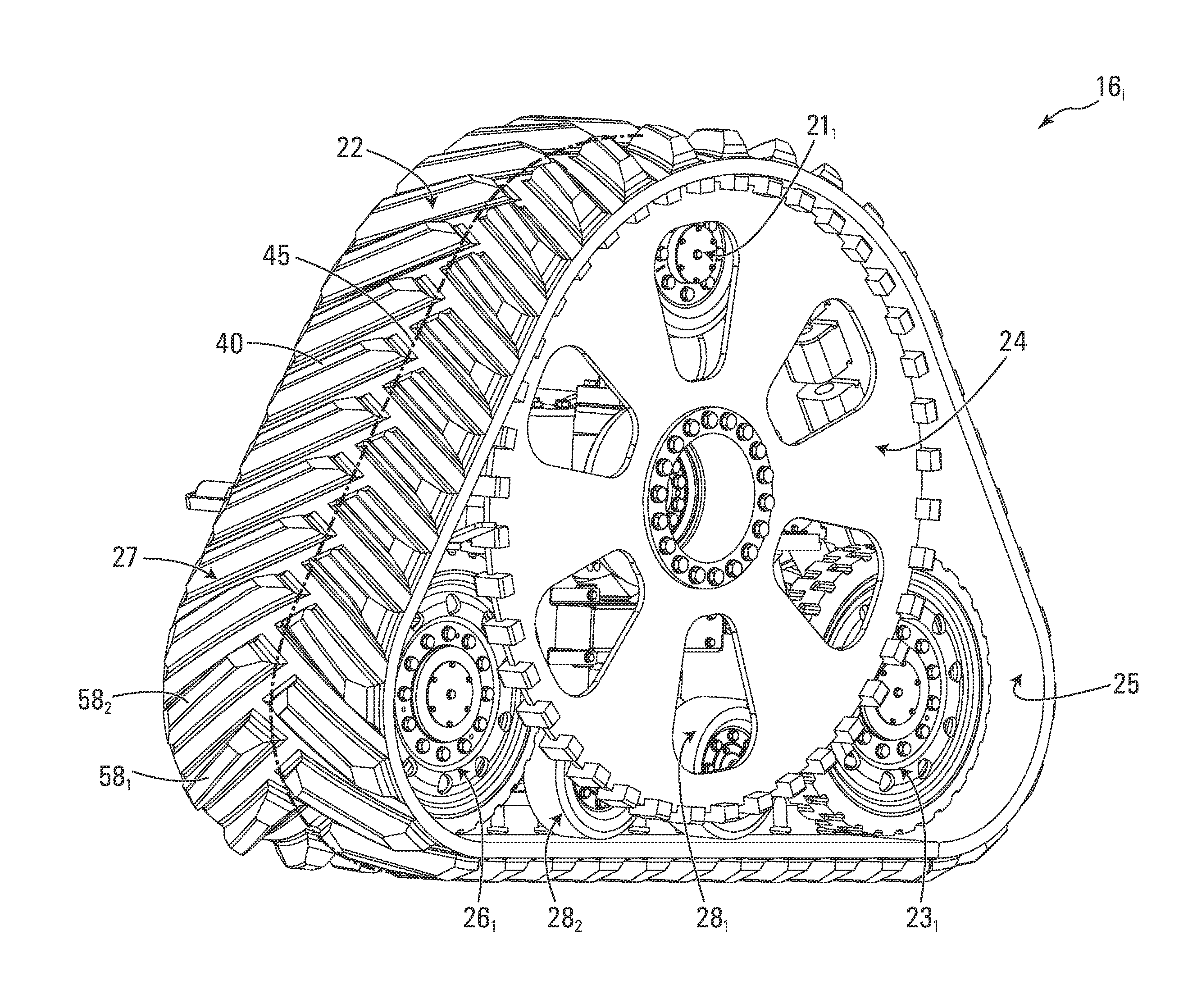
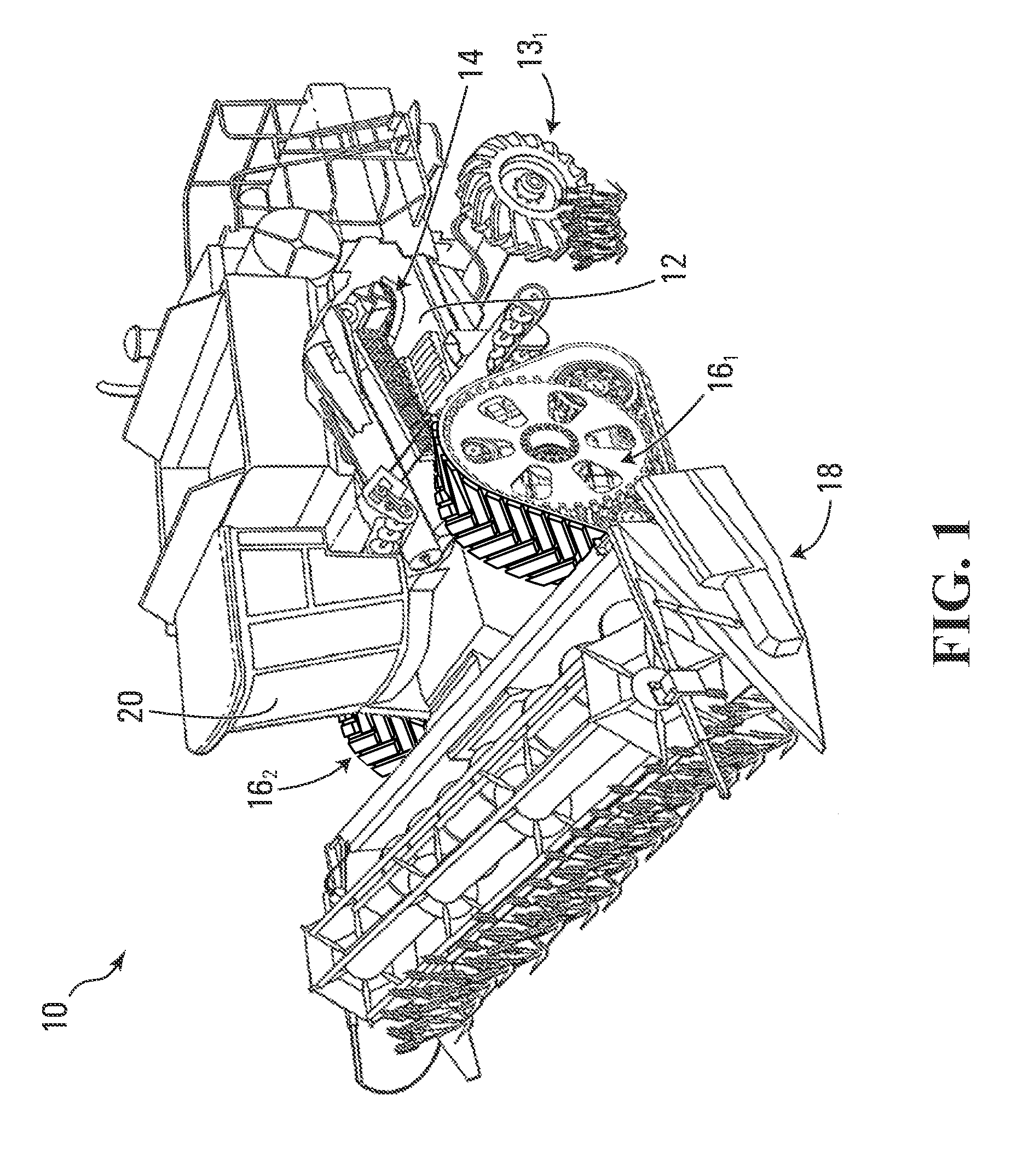
[0045]FIG. 1 shows a work vehicle 10 in accordance with an embodiment of the invention. In this embodiment, the work vehicle 10 is an agricultural vehicle for performing agricultural work. More specifically, in this example, the agricultural vehicle 10 is a combine harvester. In other examples, the agricultural vehicle 10 may be another type of harvester, a tractor or any other type of agricultural vehicle.

[0046]The agricultural vehicle 10 comprises a frame 12 supporting a prime mover 14, a plurality of track assemblies 161, 162 (which can be referred to as “undercarriages”), a plurality of ground-engaging wheels 131, 132, a working implement 18, and an operator cabin 20, which enable an operator to move the agricultural vehicle 10 on the ground to perform agricultural work.

[0047]The prime mover 14 generates motive power to move the agricultural vehicle 10. For example, the prime mover 14 may comprise an internal combustion engine and / or one or more other types of motors (e.g., an e...


PUM


Abstract

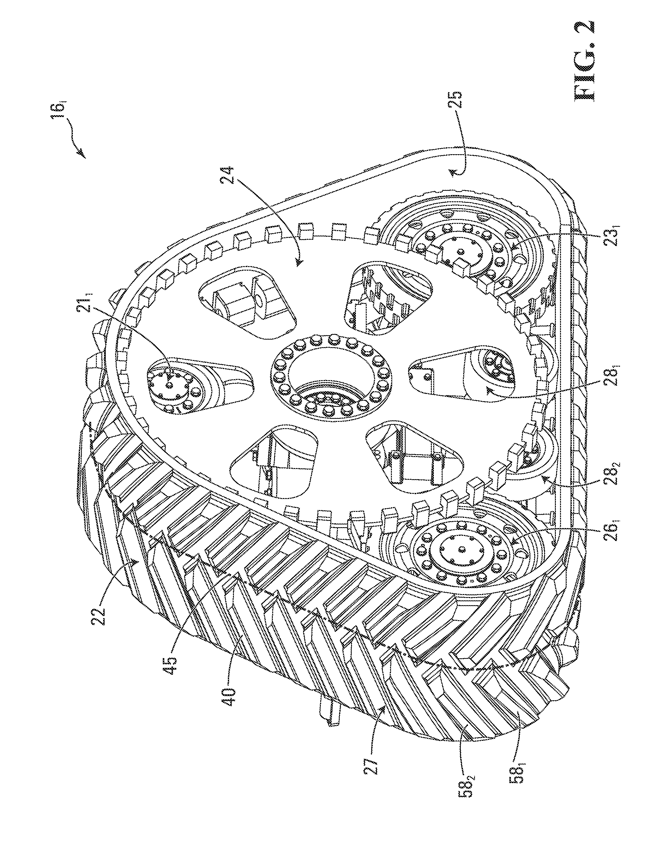
A track assembly for providing traction to a vehicle, such as an agricultural vehicle, a construction vehicle, or another work vehicle The track assembly is mountable to an axle of the vehicle The track assembly comprises a plurality of wheels comprising a leading idler wheel and a trailing idler wheel spaced apart in a longitudinal direction of the track assembly, an axis of rotation of the axle of the vehicle being located between an axis of rotation of the leading idler wheel and an axis of rotation of the trailing idler wheel in the longitudinal direction of the track assembly, and a driver wheel for rotating when the axle of the vehicle rotates The track assembly also comprises an endless track disposed around the wheels The endless track comprises an inner side facing the wheels and a ground-engaging outer side for engaging the ground The endless track engages the driver wheel such that rotation of the driver wheel imparts motion to the endless track.

Description

CROSS-REFERENCE TO RELATED APPLICATIONS[0001]This application claims priority from U.S. Patent Application No. 61 / 272,512 filed on Oct. 1, 2009 and U.S. Patent Application No. 61 / 282,834 filed on Apr. 7, 2010, which are incorporated by reference herein.FIELD OF THE INVENTION[0002]The invention relates to track assemblies for traction of vehicles operable off-road.BACKGROUND[0003]Certain work vehicles, such as agricultural vehicles (e.g., harvesters, combines, tractors, etc.), construction vehicles (e.g., loaders, bulldozers, excavators, etc.), forestry vehicles (e.g., feller-bunchers, tree chippers, knuckleboom loaders, etc.) and military vehicles (e.g., combat engineering vehicles (CEVs), etc.) to name a few, are used in agricultural fields, construction sites and other areas with a variety of ground surfaces which may be soft, slippery and / or uneven (e.g., soil, mud, sand, ice, snow, etc.).[0004]Some work vehicles ride on tires that propel them on the ground. As they are typically...

Claims


Application Information

Patent Timeline
Patent Type & Authority Applications(United States)
IPC IPC(8): B62D55/08B62D55/14B62D55/12
CPCB62D55/02B62D55/14B62D55/12B62D55/084
Inventor KAUTSCH, DEWAINELUSSIER, ALAIN
Owner CAMOPLASY INC
Learn More