Supercharge Your Innovation With Domain-Expert AI Agents!

Control apparatus for vehicle equipped with continuously variable transmission

a technology of transmission apparatus and control apparatus, which is applied in the direction of gearing control, gearing elements, gearing timing, etc., can solve the problems of late shift progression rate (advance speed) to the lowest region, late recovery response of power transfer, and late start timing of low shift control of vehicle-stop. it can improve the acceleration-performance of the vehicle and shorten the time length. , the effect of improving the time length

Inactive Publication Date: 2012-09-27
JATCO LTD +1
View PDF5 Cites 12 Cited by
  • Summary
  • Abstract
  • Description
  • Claims
  • Application Information

AI Technical Summary

Benefits of technology

The present invention provides a control apparatus for a vehicle equipped with a continuously-variable transmission that can shorten the time required to bring the pulley ratio of the transmitting mechanism toward the LOWEST side during a vehicle stop and improve the restart acceleration-performance of the vehicle if requested during the vehicle-stop LOW shift control. The control apparatus includes a drive source, a continuously-variable transmitting mechanism, a friction engagement element, and a vehicle-stop LOW shift control section that starts a vehicle-stop LOW shift control to shift the pulley ratio of the transmitting mechanism toward LOW side when the vehicle is stopped under a power-transferring state where the friction engagement element is in an engaged state and also when the pulley ratio is not in a LOWEST region. This helps to shorten the time needed to bring the pulley ratio to the LOWEST state and improve the restart acceleration-performance of the vehicle.

Problems solved by technology

(1) In the case that the vehicle stops under the D-range, even if the conditions (a) and (b) have been satisfied, it is necessary to start a releasing control for the forward clutch and then to wait until the neutral condition (c) becomes satisfied by this releasing control, in order to start the vehicle-stop LOW shift control. Thus, a start timing of the vehicle-stop LOW shift control is late (delayed).
(2) Even if the vehicle-stop LOW shift control starts, the belt-type continuously-variable transmitting mechanism is not transferring power so that static friction force (>kinetic friction force) exists between the primary pulley and the belt. That is, the primary pulley is in contact with the belt with static friction force. Hence, a vigorous force exceeding the relatively-great static friction force is necessary in order to move the belt in a radial direction of the primary pulley (in order to vary the pulley ratio toward the LOWEST side). Therefore, a shift progression rate (advance speed) to the LOWEST region is slow.
(3) If the vehicle is requested to again start to move (restart) during the vehicle-stop LOW shift control (for example, by a depressing manipulation of accelerator pedal), it is necessary to wait until the released forward clutch is engaged in order to initiate power transfer for the vehicle restart. Thus, a recovery response of power transfer is late.

Method used


Image

  • Control apparatus for vehicle equipped with continuously variable transmission
  • Control apparatus for vehicle equipped with continuously variable transmission
  • Control apparatus for vehicle equipped with continuously variable transmission

Examples


first embodiment

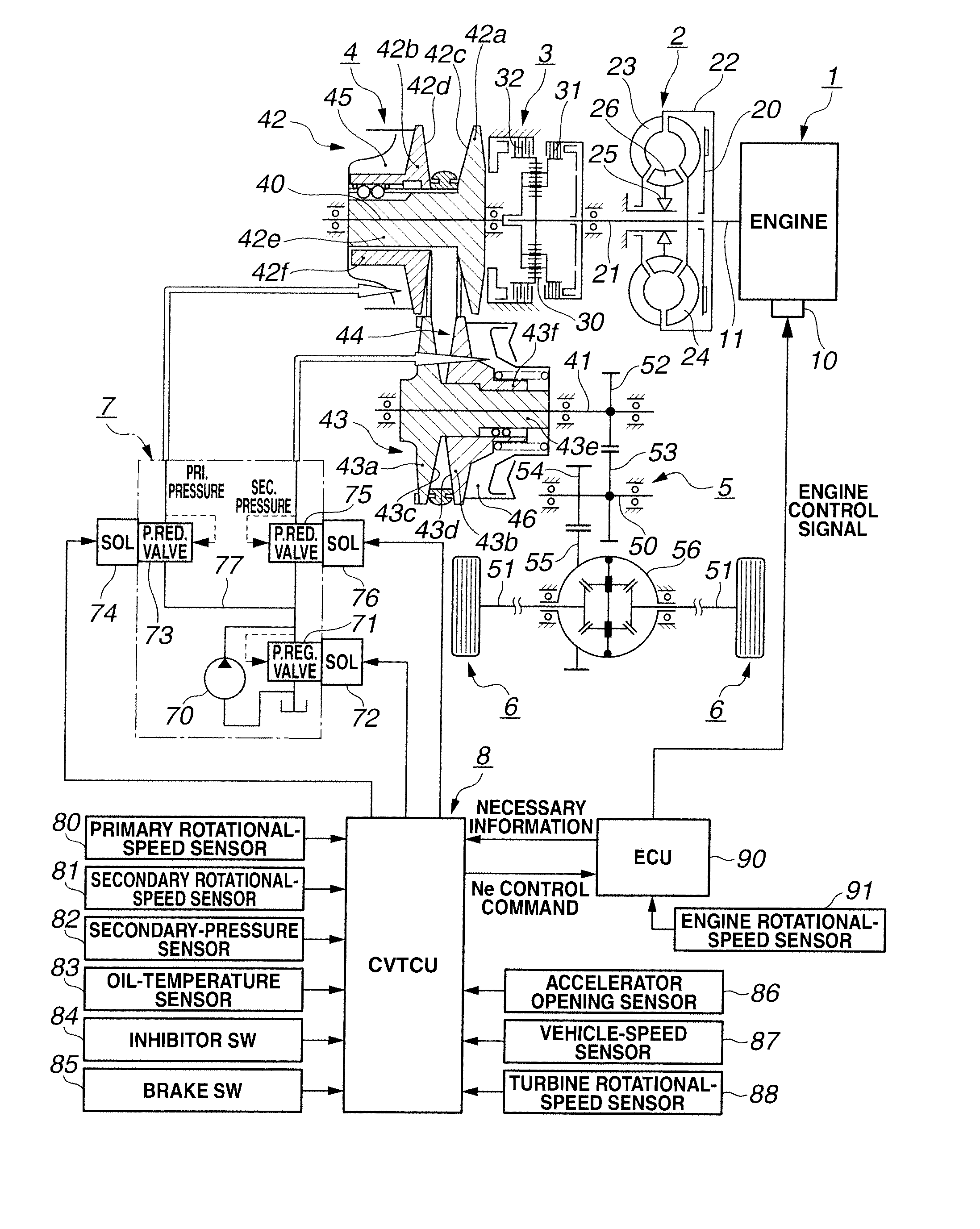
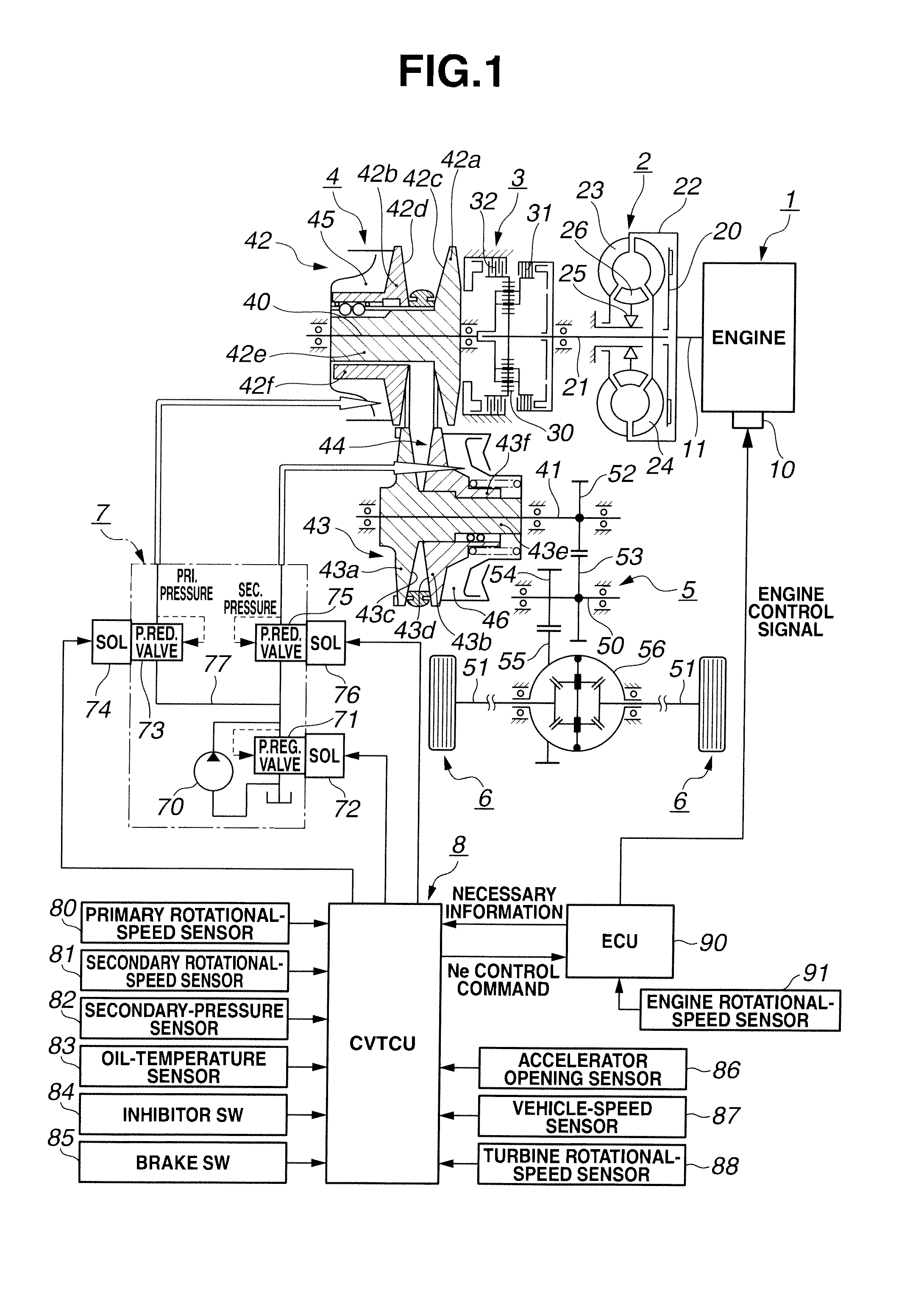
[0034]At first, a configuration will now be explained. FIG. 1 is a schematic view showing drive system and control system of an engine vehicle equipped with a belt-type continuously-variable transmission (as one example of a vehicle having a continuously-variable transmission) in the first embodiment. Hereinafter, a schematic system configuration in the first embodiment will be explained referring to FIG. 1.

[0035]As shown in FIG. 1, the drive system of the engine vehicle equipped with the belt-type continuously-variable transmission in the first embodiment includes an engine (drive source) 1, a torque converter 2, a forward / reverse switching mechanism 3, the belt-type continuously-variable transmitting mechanism (continuously-variable transmission) 4, a final reduction gear mechanism 5, and drive wheels 6 and 6.

[0036]The engine 1 includes a rotational-speed control actuator 10. The rotational-speed control actuator 10 controls an output torque of the engine 1 in accordance with an a...

second embodiment

[0147]In a second embodiment according to the present invention, the engine idle-speed increasing control is omitted from the vehicle-stop LOW shift control.

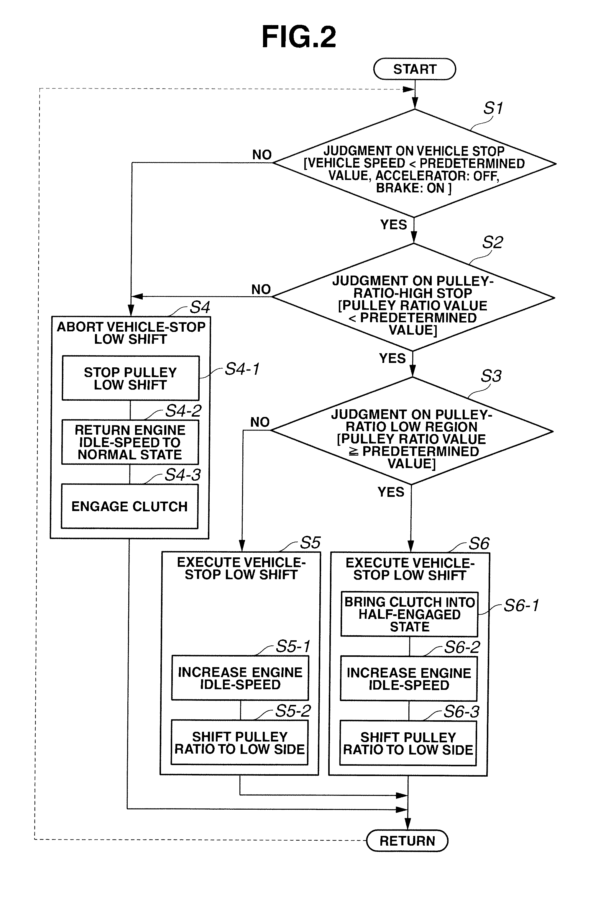
[0148]At first, a configuration will now be explained. FIG. 7 is a flowchart (vehicle-stop LOW shift control means or section) showing flow and configuration of processing of the vehicle-stop LOW shift control which is executed by the CVT control unit 8 in the second embodiment. Respective steps of FIG. 7 will now be explained. Since step S21, step S22 and step S23 of FIG. 7 are same as step S1, step S2 and step S3 of FIG. 2, explanations thereof will be omitted for purpose of simplification of the disclosure.

[0149]At step S24 subsequent to step S21 or step S22, the control unit (the CVT control unit 8) carries out a vehicle-stop LOW shift aborting control in a case that the vehicle-stop LOW shift control (the pulley LOW shift control and / or the clutch half-engagement control) is currently being carried out. Then, the program is...

third embodiment

[0170]In a third embodiment according to the present invention, the power-transfer amount of the forward clutch 31 is gradually reduced toward a target power-transfer amount for the forward clutch 31 under the clutch half-engagement control.

[0171]At first, a configuration will now be explained. FIG. 9 is a flowchart (vehicle-stop LOW shift control means or section) showing flow and configuration of processing of the vehicle-stop LOW shift control which is executed by the CVT control unit 8 in the third embodiment. Respective steps of FIG. 9 will now be explained. Since respective steps S31-S35 of FIG. 9 are same as steps S1-55 of FIG. 2, explanations thereof will be omitted for purpose of simplification of the disclosure.

[0172]At step S36 subsequent to step S33, the control unit carries out a vehicle-stop LOW shift control (the clutch half-engagement control, the engine idle-speed increasing control and the pulley LOW shift control). Then, the program is returned. At step 36, the ve...


PUM


Abstract

A control apparatus for a vehicle equipped with continuously-variable transmission includes a drive source; a continuously-variable transmitting mechanism including a primary pulley, a secondary pulley and a power transferring member; a friction engagement element provided between the drive source and the continuously-variable transmitting mechanism; and a vehicle-stop LOW shift control section including a vehicle-stop judging section configured to judge if the vehicle is in a stopped state. A power-transferring state of the friction engagement element is controlled by an engaging-force control. The vehicle-stop LOW shift control section starts a vehicle-stop LOW shift control to shift a pulley ratio of the continuously-variable transmitting mechanism toward LOW side when the vehicle-stop judging section determines that the vehicle is stopped under a power-transferring state where the friction engagement element is in an engaged state and the pulley ratio is not in a LOWEST region.

Description

BACKGROUND OF THE INVENTION[0001]The present invention relates to a control apparatus for a vehicle equipped with continuously-variable transmission, adapted to perform a vehicle-stop LOW shift control that shifts a pulley ratio toward LOW side at the time of vehicle stop.[0002]In the case of a vehicle equipped with belt-type continuously-variable transmission, there is a possibility that the vehicle stops under a state where the pulley ratio has not yet returned to its LOWEST state in dependence upon driver's manipulations, a road-surface state and the like, for example, when a pattern of running (moving)→deceleration→stop→restart has been repeated. After the vehicle has stopped under a pulley-ratio state other than the LOWEST state, if trying to restart the vehicle under this pulley-ratio state, a torque sufficient to start to move the vehicle is not secured. Hence, an acceleration performance for vehicle restart is inferior.[0003]U.S. Patent Application Publication No. 2002-07244...

Claims


Application Information

Patent Timeline
Patent Type & Authority Applications(United States)
IPC IPC(8): B60W10/107
CPCF16H37/022F16H61/66259Y10T477/6203Y10T477/62427F16H2312/14F16H61/66F16H61/02
Inventor ISHIDA, KAZUKITANAKA, HIROYASUKIMURA, YUSUKEIZUMI, TETSUYASUZUKI, AKITOEGUCHI, TAKASHIMIYAISHI, HIRONORI
Owner JATCO LTD
Features
  • R&D
  • Intellectual Property
  • Life Sciences
  • Materials
  • Tech Scout
  • Unparalleled Data Quality
  • Higher Quality Content
  • 60% Fewer Hallucinations
Learn More