Dynamic display optimization method and system with image motion

Inactive Publication Date: 2006-11-16
L 3 COMM CORP
View PDF21 Cites 35 Cited by
  • Summary
  • Abstract
  • Description
  • Claims
  • Application Information

AI Technical Summary

Benefits of technology

[0011] It is therefore an object of the present invention to provide a method that reduces or avoids the problem of perceived separation of the bit planes, and allows for an improvement of the display of video displayed using bit planes. This object is accomplished by a method that comprises detecting when artifact-causing movement conditions are present in which problems with bit-plane displays occur, such as increased image movement or rapid head movement of the user, and th

Problems solved by technology

In some environments, however, such as simulators for aircraft, bit-plane displays can be subject to some undesirable perception effects where the video being displayed has certain characteristics, or when the user's eyes pan or track across the image, so as to result in relatively rapid movement of the eye of the viewer relative to the objects seen in the displayed imagery.
As illustrated in by FIG. 1, the effect of this on the user's eye moving continuously relative to the object is that the image of an

Method used


Image

  • Dynamic display optimization method and system with image motion
  • Dynamic display optimization method and system with image motion
  • Dynamic display optimization method and system with image motion

Examples


Example

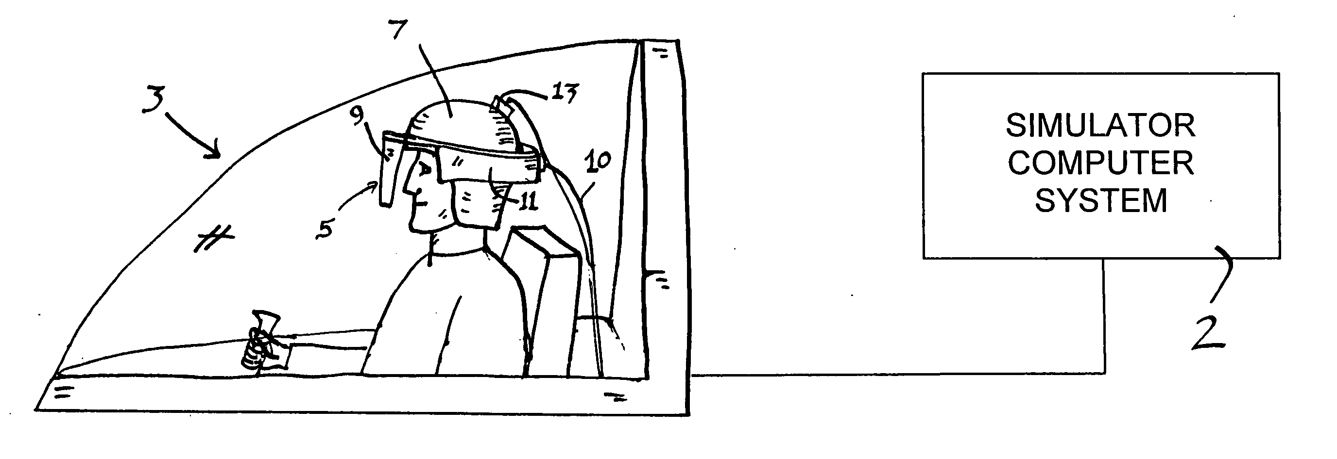
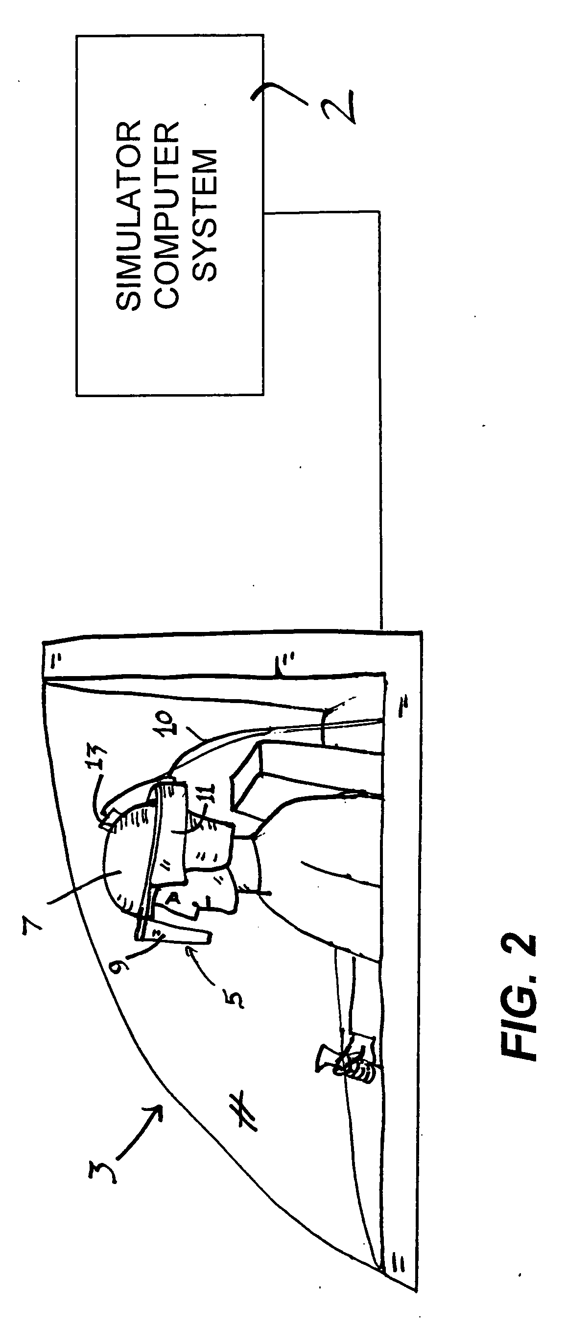
[0027] As best seen in FIG. 2, in a simulator system for an aircraft, the user is seated in a simulated cockpit structure 3 that includes dummy controls and gauges similar to those in the real aircraft. A simulator computer system 2 controls the operation of the simulator system to make the simulation as realistic as possible. The simulator system also includes a display system that gives the user a simulated real-time out-the-window (OTW) view that is created by the simulator computer system 2, which includes an image generation system in the form of hardware and software that renders imagery video fast enough to keep up with the real-time operation of the simulation. The display may be a projection system, such as the system shown in U.S. Pat. No. 6,552,699, or any of a variety of other projection or display systems. In the preferred embodiment, the display system is a head-mounted display system 5 supported on a helmet 7 on the head of the user. The head-mounted display system 5 ...


PUM


Abstract

A system displays video to a user and has a display device with a field of pixels. It displays video to the user in the form of a series of discrete sequential frame images each made up of a first predetermined number of bit planes in which the pixels of the display are either off or have a color and intensity that is uniform over the field of pixels. The apparatus detects when a movement condition is present, such as rapid head movement or an object in the video crossing the display rapidly, in which condition the user's eye may tend to track across the display device at a rate at which perception of the video displayed may be reduced in quality, and it generates a condition-present signal when such a movement condition is detected. Responsive to generation of said condition-present signal, the apparatus causes the display device to display the frame images using fewer bit planes for each frame image than when said movement condition is not detected. Display with the original number of bit planes returns when the movement condition is over.

Description

FIELD OF THE INVENTION [0001] This invention relates to systems and methods for displaying video to a user, and especially to systems that involve displaying video images using sequentially-displayed bit planes. BACKGROUND OF THE INVENTION [0002] As is well known in the art, video is displayed to a viewer by displaying a series of still frame images sequentially on a display. The images are displayed one after another at a rate that is fast enough so that it appears to the normal human eye that the movement of objects in the video is smooth and continuous. In digital video, each frame image is made up of pixels that each have a respective color intensity for each of the primary display colors (red, green, and blue). The digital value of each primary color intensity of the pixel is frequently defined by eight bits of data, allowing for definition of up to 255 levels of intensity for each color, and an eight-bit color depth of a possible 255×255×255=16,581,375 colors, ranging from bla...

Claims


Application Information

Patent Timeline
IPC IPC(8): G09G5/10
CPCG09B9/307H04N9/3179H04N9/3194
Inventor TURNER, JAMES A.
Owner L 3 COMM CORP
Why Eureka
Try Eureka