
Systems and methods for managing an energy distribution network

a technology of energy distribution network and management method, applied in non-electric variable control, process and machine control, instruments, etc., can solve the problems of increasing the capacity of electricity generation, requiring many years of planning and construction, and reducing energy consumption

Inactive Publication Date: 2012-09-27
GENERAL ELECTRIC CO
View PDF2 Cites 13 Cited by
  • Summary
  • Abstract
  • Description
  • Claims
  • Application Information

AI Technical Summary

Problems solved by technology

Increasing electricity generation capacity can be capital intensive and take many years of planning and construction.
In the context of a residential application, for example, this means that during peak demand periods, the utility may choose to not supply electricity to the residential hot water heater.
Such broadcasted demand response requests may not necessarily reduce energy consumption in the specific portions of the power distribution network that experience reduced power distribution and / or transmission capacity.
In addition, while some utility customers may be willing to subscribe to a rate structure that enables the utility to disconnect energy supply to certain appliances / equipment during peak periods, such rate structures are not necessarily satisfactory.

Method used


Image

  • Systems and methods for managing an energy distribution network
  • Systems and methods for managing an energy distribution network
  • Systems and methods for managing an energy distribution network

Examples


Embodiment Construction

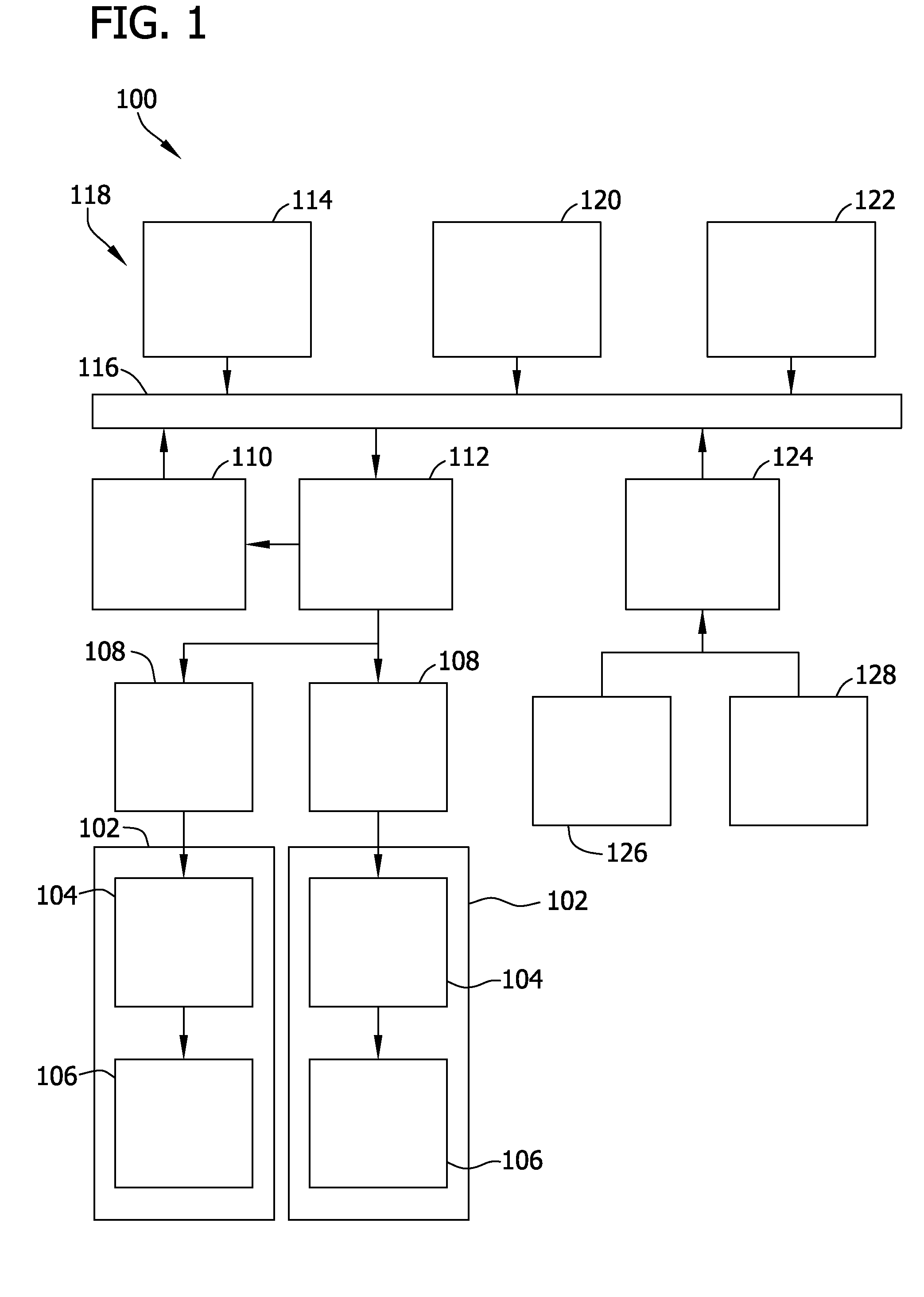
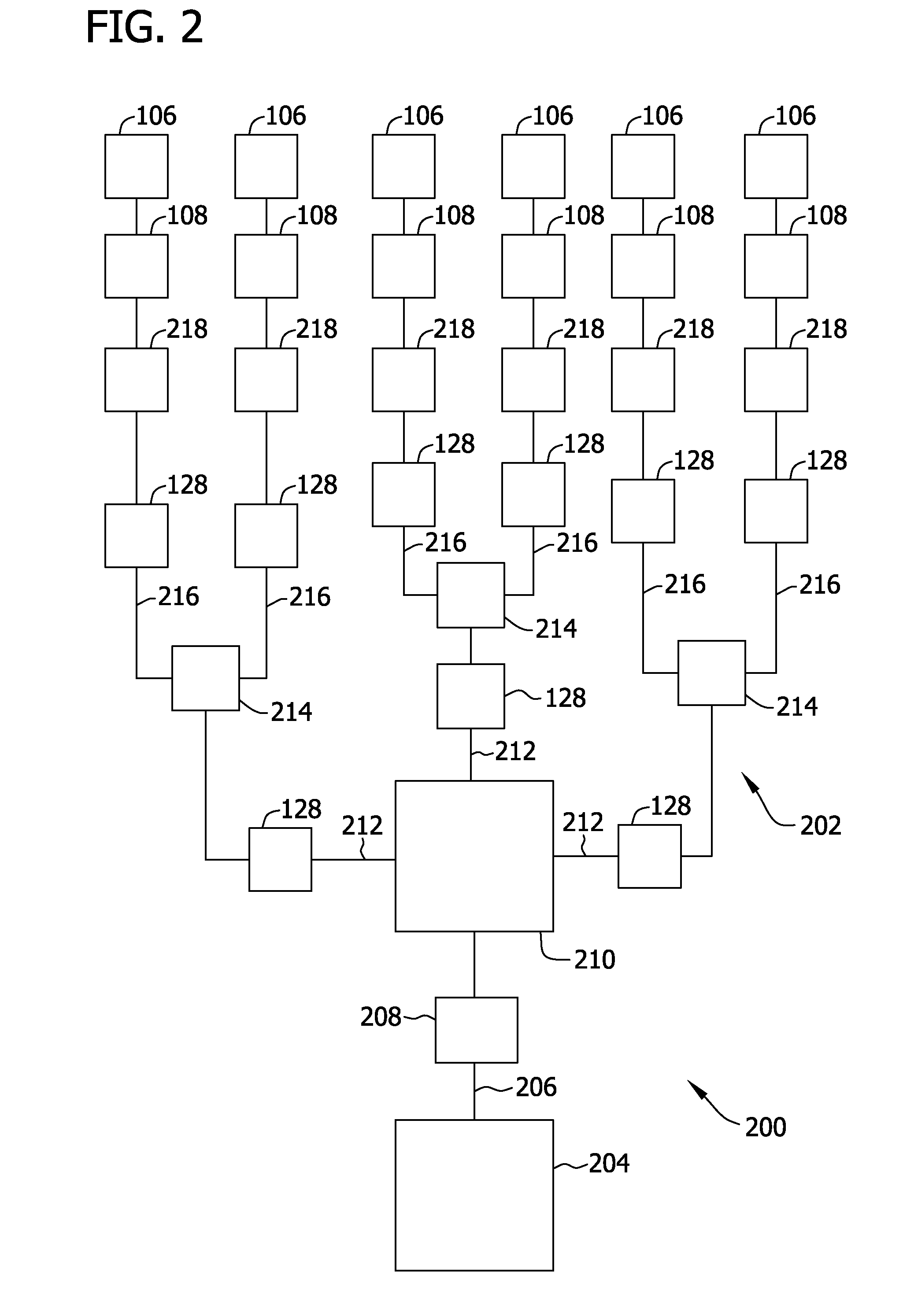
[0015]FIG. 1 illustrates an exemplary system 100 that may be used with a utility company (not shown), such as an electric utility company. Moreover, in the exemplary embodiment, the utility company provides energy, such as electricity, to a plurality of locations 102. Alternatively, energy provided by the utility company may include natural gas, propane, and / or any other form of energy and / or product usable for generating energy. Locations 102 may include, but are not limited to only including, a residence, an office building, an industrial facility, and / or any other building or location that receives energy from the utility company. In the exemplary embodiment, system 100 monitors the delivery of energy from the utility company to locations 102.

[0016]In the exemplary embodiment, each location 102 includes at least one network device 104 and at least one energy consumer 106 coupled to network device 104. As used herein, the term “couple” is not limited to a direct mechanical and / or ...


PUM


Abstract

A system includes a first computer including an energy distribution network model. The first computer identifies a plurality of energy consumers associated with an energy distribution constraint within the energy distribution network. The system also includes a second computer configured to receive data from the first computer. The second computer is also configured to identify a plurality of customers subscribed to a demand response program and identify a subset of the plurality of energy consumers that are associated with the plurality of customers. The second computer is further configured to identify a device associated with each energy consumer of the subset of energy consumers and cause a demand response request to be transmitted to at least one identified device.

Description

BACKGROUND OF THE INVENTION[0001]The present application relates generally to energy systems and, more particularly, to systems and methods for managing an energy distribution network.[0002]Demand for electricity by customers generally varies over the course of any particular day. Such demand also generally varies by season (e.g., demand for electricity may be higher during the hot summer months as compared to the demand in the more mild spring months). Such demand may also grow over time in a particular market as the population and / or industry grows. Increasing electricity generation capacity can be capital intensive and take many years of planning and construction.[0003]Rather than undertake such significant capital investments, planning and construction, some utilities impose a rate structure that discourages use of electricity during peak demand periods. For example, a utility customer who subscribes to such a rate structure agrees to reduced energy consumption during such peak ...

Claims


Application Information

Patent Timeline
Patent Type & Authority Applications(United States)
IPC IPC(8): G06F1/26
CPCH02J3/14Y04S20/222Y02B70/3225H02J2310/60H02J3/144
Inventor LITTRELL, NATHAN BOWMAN
Owner GENERAL ELECTRIC CO
Learn More