Work Vehicle

a technology for working vehicles and rotors, applied in the field of work vehicles, can solve the problems of rotors being sharply displaced, difficult to adjust the position of rotors, and taking time and effort to operate the pipe arrangemen

Active Publication Date: 2012-10-04
KUBOTA LTD
View PDF35 Cites 45 Cited by
  • Summary
  • Abstract
  • Description
  • Claims
  • Application Information

AI Technical Summary

Benefits of technology

[0021]An object of the present invention is to provide a rational construction for a vehicle including a power unit and an air conditioner.

Problems solved by technology

As a result, pipe arrangement operation would take time and effort.
However, from the viewpoint of cooling the power control unit satisfactorily, it is not preferable to arrange the power control unit in the interior of the vehicle.
As a result, it would be difficult to adjust the position of the rotor, that is, the rotor would be sharply displaced, for example.
If the rotor sticks to the inner periphery of the stator in this way, disconnecting the rotor from the stator would be difficult and troublesome.

Method used


Image

  • Work Vehicle
  • Work Vehicle
  • Work Vehicle

Examples


Embodiment Construction

[0109]An embodiment of the present invention will be described hereinafter in reference to the accompanying drawings.

[Overall Construction]

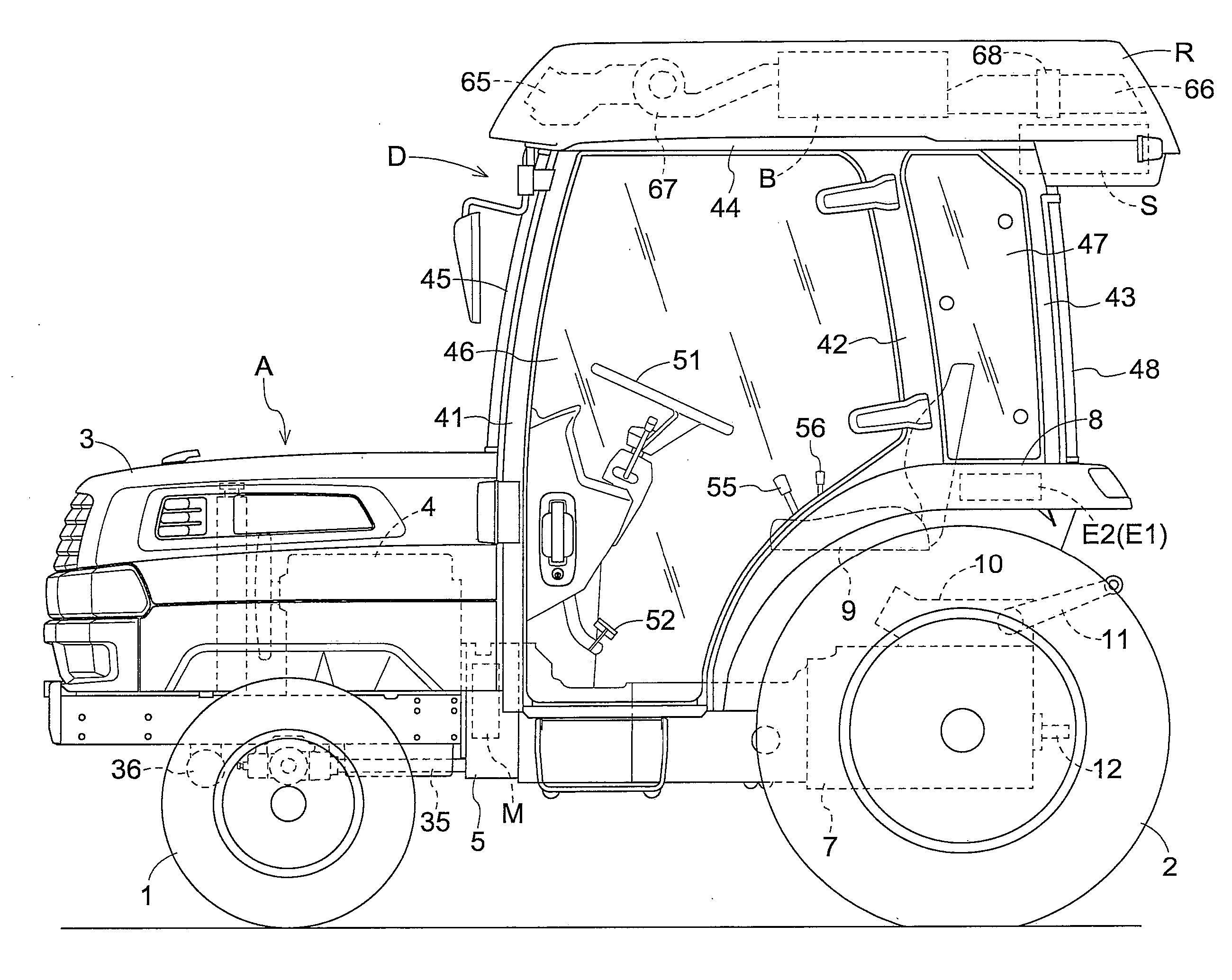
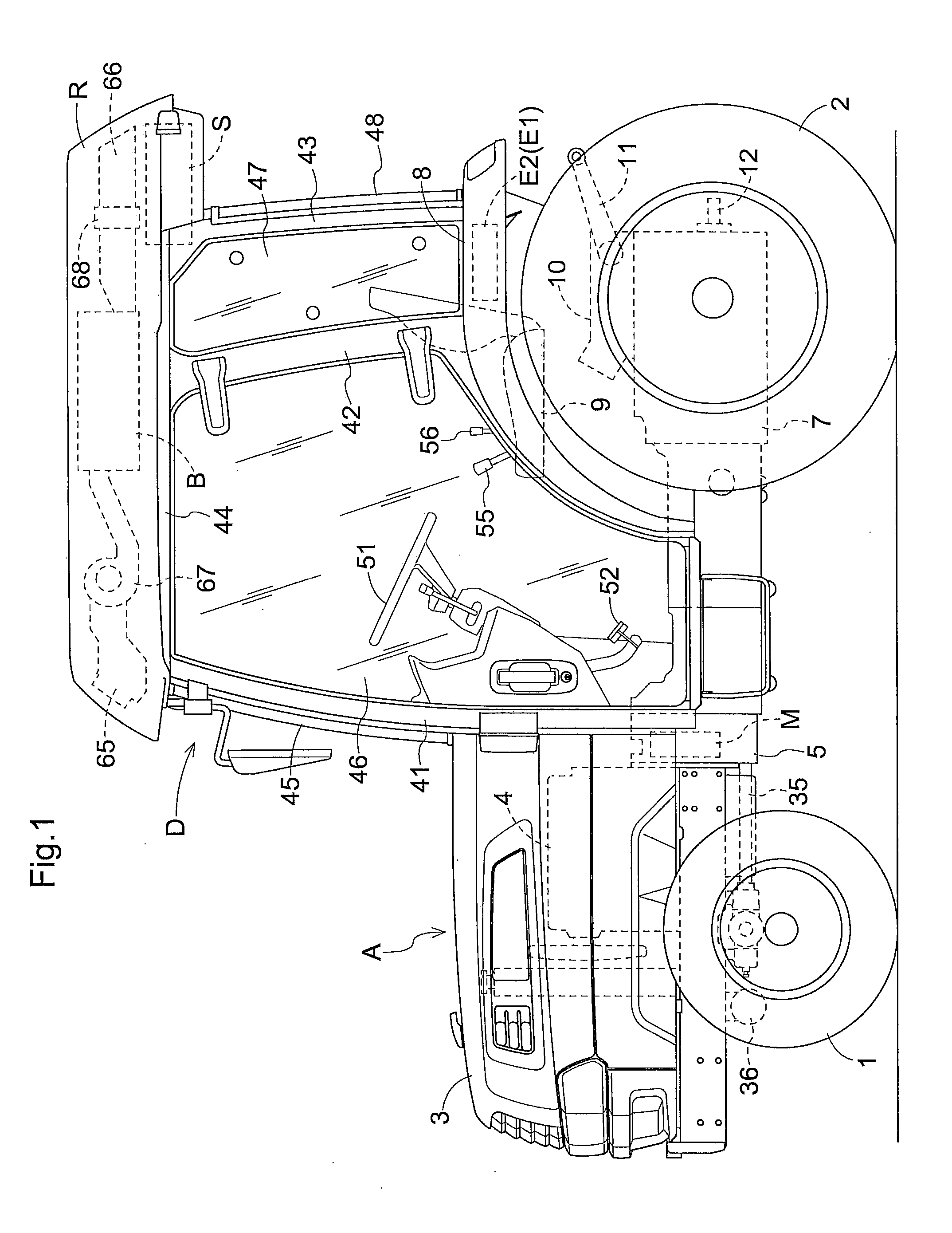
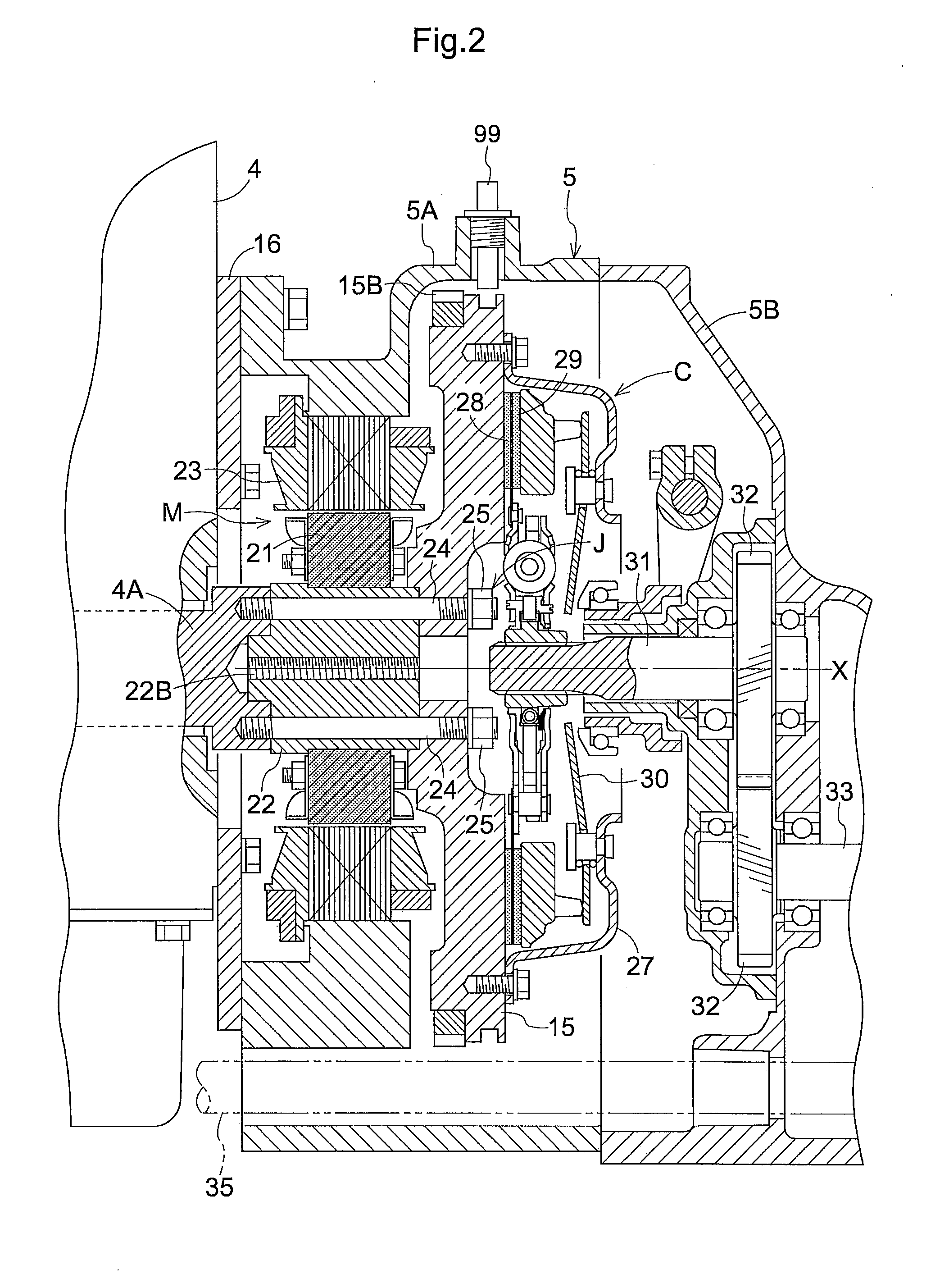
[0110]As shown in FIG. 1, a hybrid-type tractor acting as a work vehicle comprises a propelling vehicle body A including a pair of right and left front steerable wheels 1 and a pair of right and left rear wheels 2, an engine hood 3 mounted forwardly of the propelling vehicle body A and having a diesel-type engine 4 therein, a transmission housing 5 mounted in a rear side of the engine 4 for accommodating a generator motor M (an example of an electric motor) and a main clutch mechanism C, a transmission case 7 connected to a rear surface of the transmission housing 5, right and left rear fenders 8 provided rearwardly of the propelling vehicle body A to project laterally outwardly from the propelling vehicle body A to cover above the right and left rear wheels 2, a driver's seat 9 provided between the right and left rear fenders 8, and a cabin D pr...


PUM


Abstract

A work vehicle comprising, a power unit, an electric motor activated by electric power from the power unit, a propelling transmission system for receiving drive power from the electric motor, a cabin including a roof portion the driver rides, an air conditioner for adjusting air temperature in the interior of the cabin. the power unit and the air conditioner are provided in the roof portion of the cabin.

Description

TECHNICAL FIELD[0001]The present invention relates to a work vehicle for transmitting drive power from an electric motor activated by electric power from a power unit to a propelling transmission system, and more particularly to improvement of an arrangement of the power unit.RELATED ART[0002]An example of the work vehicle having the above-noted construction is disclosed in Japanese Unexamined Patent Application Publication No. 2004-66889 in which a power unit (a battery unit in the publication) is provided in a top surface of a vehicle body of an electric-powered bus such as an electric car or a hybrid electric car. With such an arrangement, vehicle-running air is directed to the battery unit, thereby to cool the battery unit.[0003]As described in Japanese Unexamined Patent Application Publication No. 2004-66889 in which the power unit is mounted in the roof portion, there is no need to secure a space for arranging the power unit within the vehicle body, as a result of which ambien...

Claims


Application Information

Patent Timeline
Patent Type & Authority Applications(United States)
IPC IPC(8): B60K1/04B60K6/40B60K17/00B62D33/06B60K6/20B60L50/10B60L50/16B60L50/30
CPCB60H1/00207Y02T10/7291B60K1/04B60K17/10B60K2001/005B60Y2200/22B60Y2200/221B60Y2200/92B60Y2400/61B60H1/00378B60H2001/00235B60L1/003B60L1/08B60L11/16B60L11/1874B60L11/1877B60L15/2054B60L2200/40B60L2240/34B60L2240/36B60L2240/441B60L2240/545B60L2240/662Y02T10/7005Y02T10/705Y02T90/16Y02T10/7027Y02T10/7275B60K1/00Y02T10/72A01B63/1013B60K17/04B60L50/10B60L50/30B60L58/26B60L50/66Y10S903/951Y02T10/70Y02T10/64Y02T90/12Y02T10/7072Y02T90/14B60L53/53B60L53/18B60H1/00278B60H1/00385B60H1/00564B60L15/007B60R16/02
Inventor ICHIKAWA, NOBUSHIGE
Owner KUBOTA LTD
Why Eureka
Try Eureka