
Snowmobile Suspension

a suspension and snowmobile technology, applied in the direction of sledges, vehicle components, rider propulsion, etc., can solve the problems of less discomfort for operators and passengers, affecting steering, and reducing the effect of weight transfer

Active Publication Date: 2012-10-04
BOMBARDIER RECREATIONAL PROD INC
View PDF1 Cites 13 Cited by
  • Summary
  • Abstract
  • Description
  • Claims
  • Application Information

AI Technical Summary

Benefits of technology

The present invention provides a rear suspension assembly for a tracked snowmobile that reduces the effect of weight transfer during acceleration and deceleration. The assembly includes a rail for engagement with the endless drive track, a first suspension arm, a second suspension arm, a bracket arm, a link, a first shock absorber, a second shock absorber, a tie rod, and a front suspension arm. The rear suspension assembly is connected to the front suspension arm and the chassis of the snowmobile. The invention provides a more stable and comfortable ride for the snowmobile and reduces the impact of uneven surfaces on the vehicle's performance.

Problems solved by technology

Irregularities in the terrain over which a tracked vehicle travels produce displacements and deflections of its suspension system.
Depending upon their magnitude, frequency and strength, these deflections cause more or less discomfort to the operator and passenger of the snowmobile.
This tends to lift the skis off the ground and thus interferes with steering.
The internal forces developed during rapid deceleration cause, however, a weight transfer from the rear of the vehicle to the front.

Method used


Image

  • Snowmobile Suspension
  • Snowmobile Suspension
  • Snowmobile Suspension

Examples


first embodiment

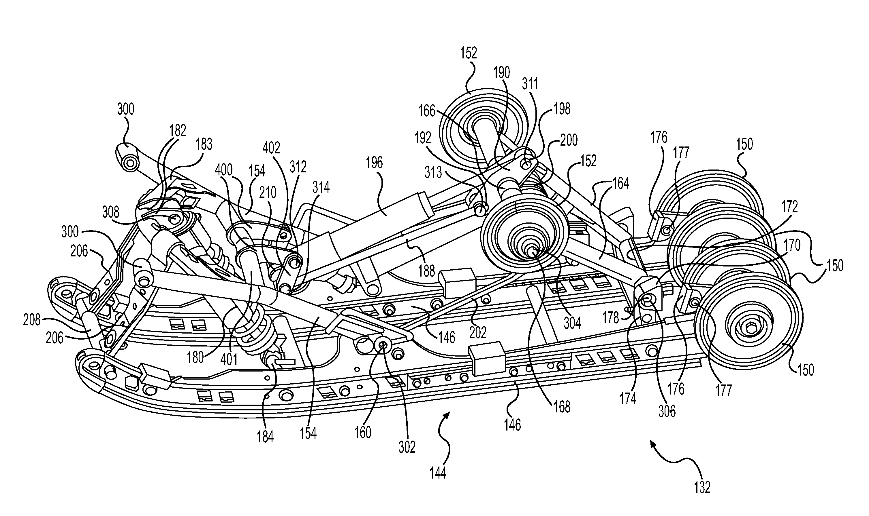
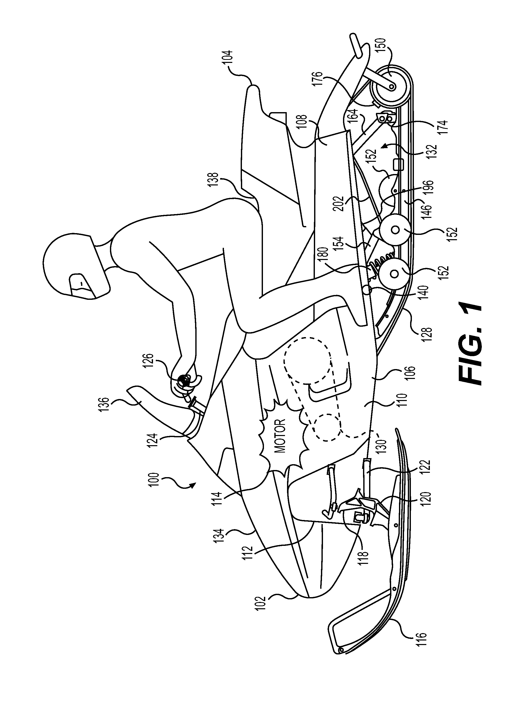
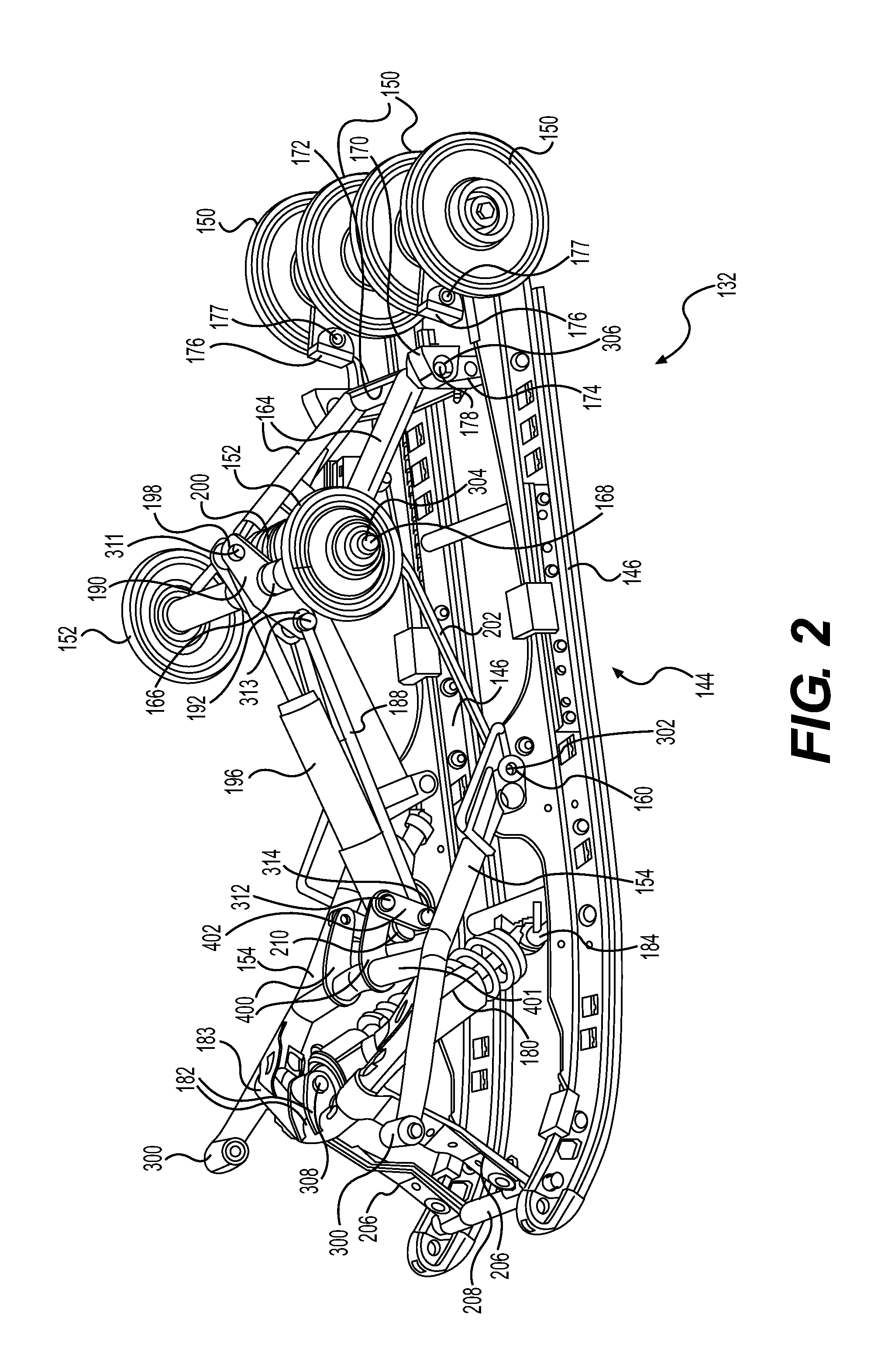
[0050]Referring to FIGS. 2 to 5, the rear suspension assembly 132 according to the invention will now be described in greater details. The rear suspension assembly 132 comprises left and right front suspension arms 154 and left and right rear suspension arms 164. It is contemplated that the left and right rear suspension arms 164 could be welded together to form a single rear suspension arm.

[0051]The front suspension arms 154 extend downwardly and rearwardly from a front portion 220 of the tunnel 108. Upper ends of the front suspension arms 154 are pivotally attached to the tunnel 108 at pivot points 300 to form a pivot axis 301 (shown in FIG. 3) that is perpendicular to the longitudinal axis 109 of the tunnel 108. The lower ends of the front suspension arms 154 are each pivotally attached to their respective slide rails 146 of the slide frame assembly 144 by a pivot pin assembly 160 at pivot point 302. Left and right pivot points 302 define a pivot axis 303 (shown in FIG. 3) perpen...

second embodiment

[0071]Referring to FIGS. 8 to 10, a rear suspension assembly 132′ according to the invention will now be described in greater details. For ease of understanding, elements of the rear suspension assembly 132′ similar to the rear suspension assembly 132 will have the same reference numeral followed by a prime sign.

[0072]The rear suspension assembly 132′ comprises left and right front suspension arms 154′ and a single rear suspension arm 164′. It is contemplated that the rear suspension assembly 132′ could comprise a pair of rear suspension arms 164′ .

[0073]The front suspension arms 154′ extend downwardly and rearwardly from the front portion 220 of the tunnel 108. Upper ends of the front suspension arms 154 are pivotally attached to the tunnel 108 at pivot points 300′ to form a pivot axis 301′ that is perpendicular to the longitudinal axis 109 of the tunnel 108. Lower ends of the front suspension arms 154′ are each pivotally attached to their respective slide rails 146 of the slide fr...


PUM


Abstract

A suspension system for a snowmobile comprises first and second suspension arms pivotally connected to a chassis and to a rail, and extending forwardly and upwardly from the rail. A bracket arm is fixedly connected to the first suspension arm. A link is pivotally connected to the bracket arm. A first shock absorber is pivotally connected to the first suspension arm and to the rail. The lower end of the first shock absorber is disposed forwardly of the lower end of the first suspension arm. A second shock absorber is pivotally connected to the link and to second suspension arm. The lower end of the second shock absorber is disposed rearwardly of the lower end of the first shock absorber. A tie rod is pivotally connected to the link, and to the second suspension arm. A snowmobile having such suspension system is also disclosed.

Description

FIELD OF THE INVENTION[0001]The present invention relates to suspension assemblies for tracked vehicles, and more particularly to rear suspension assemblies for snowmobiles.BACKGROUND OF THE INVENTION[0002]Irregularities in the terrain over which a tracked vehicle travels produce displacements and deflections of its suspension system. Depending upon their magnitude, frequency and strength, these deflections cause more or less discomfort to the operator and passenger of the snowmobile.[0003]The dynamic response of a rear suspension assembly of a tracked vehicle such as a snowmobile, to the multitude of loads imposed upon it during operation, has a significant effect on the overall performance of the vehicle and rider comfort. Different types of loads are regularly exerted upon a tracked vehicle. A first type of loads results from impact loads imposed upon the rear suspension as the vehicle travels over rough terrain and encounters bumps, these are of the most concern. A second type o...

Claims


Application Information

Patent Timeline
Patent Type & Authority Applications(United States)
IPC IPC(8): B62B17/00B62M27/02
CPCB62M2027/026B62M27/02
Inventor FECTEAU, BERTHOLDTHIBAULT, SEBASTIENMALLETTE, BERTRAND
Owner BOMBARDIER RECREATIONAL PROD INC
Learn More