Reconfigurable antenna system for radio frequency identification (RFID)

a radio frequency identification and reconfigurable technology, applied in the direction of antennas, non-resonant long antennas, sensing record carriers, etc., can solve the problems of limited prior art systems, difficult to properly expose the transponder to the radiated electromagnetic field and identify it with standard rfid antennas, and limited antenna range. , to achieve the effect of increasing the reading reliability of rfid systems

Active Publication Date: 2012-10-04
GPI SPA
View PDF16 Cites 14 Cited by
  • Summary
  • Abstract
  • Description
  • Claims
  • Application Information

AI Technical Summary

Benefits of technology

[0007]In order to overcome the aforementioned problems in the art, an antenna system is proposed that allows increasing the reading reliability of RFId systems by changing the shape and / or the polarization of the electromagnetic field radiated by the antennae. By dynamically changing the direction in which the energy is radiated and / or the polarization and / or the shape of the radiated field, the electromagnetic field can be “moved” so as to read tags that receive faint signals with standard RFId systems. Polarization alignment between the reader's antenna and the transponder allows for maximum power transfer, while changing the direction and / or shape of radiation allows concentrating the electromagnetic field towards the transponder.
[0010]By using pattern and / or polarization reconfigurable antennas, the invention makes it is possible to increase the reading reliability and the ease of installation of RFId systems with respect to current solutions in scenarios like supply chain, warehouse, manufacturing, retail, asset and people tracking, and medical applications.

Problems solved by technology

However in the case of high tag density or when tags are used with non-compliant RFId materials (e.g. liquid, metal) or when they are applied on goods that can not be moved, it is difficult to properly expose the transponder to the radiated electromagnetic field and identify it with standard RFId antenna system.
However, such prior art systems are limited in that they do not permit the shape and polarization of the electromagnetic field to be changed so as to concentrate the electromagnetic field towards the transponder to more effectively and efficiently read RFid tags that may otherwise be difficult to read.
Moreover, such prior art systems do not allow for efficient power transfer, thereby limiting the range of the antenna systems.

Method used


Image

  • Reconfigurable antenna system for radio frequency identification (RFID)
  • Reconfigurable antenna system for radio frequency identification (RFID)
  • Reconfigurable antenna system for radio frequency identification (RFID)

Examples


Embodiment Construction

[0022]A detailed description of illustrative embodiments of the present invention will now be described with reference to FIGS. 1-9. Although this description provides a detailed example of possible implementations of the present invention, it should be noted that these details are intended to be exemplary and in no way delimit the scope of the invention.

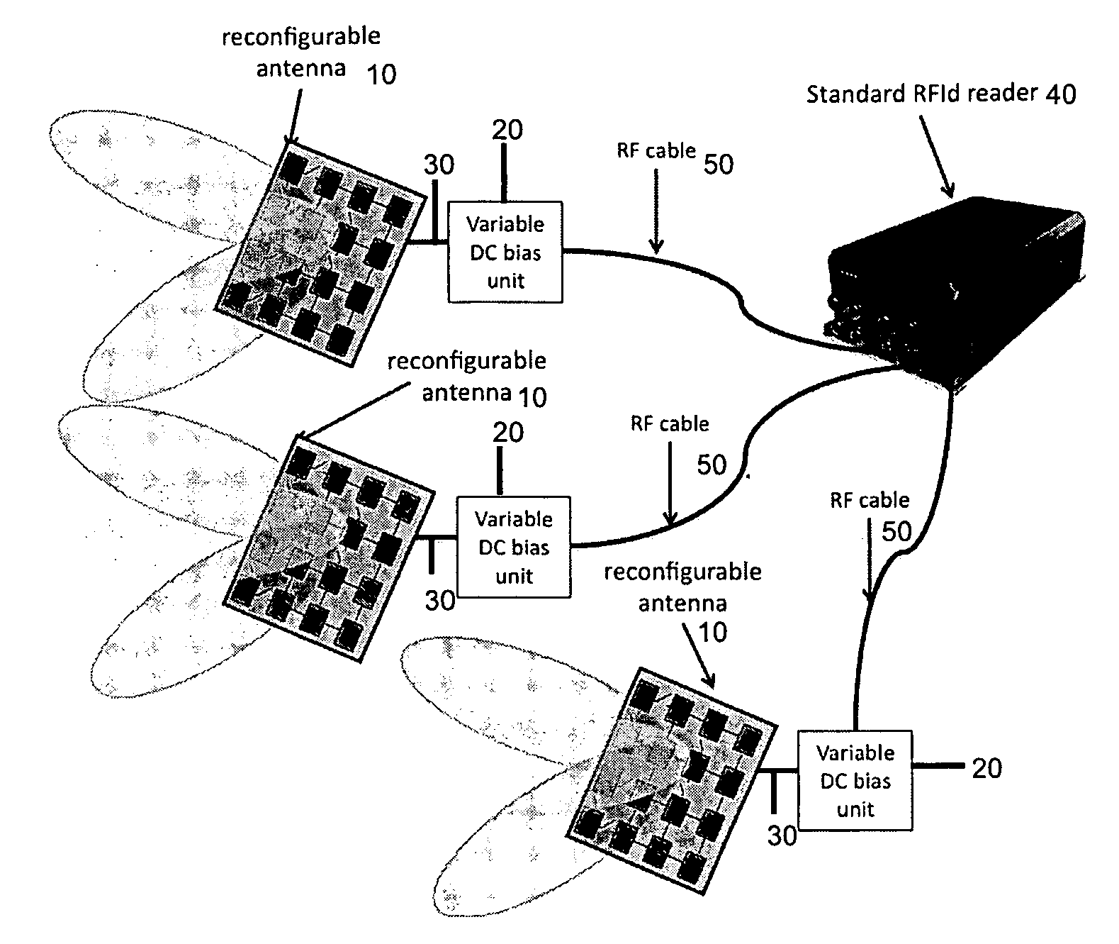
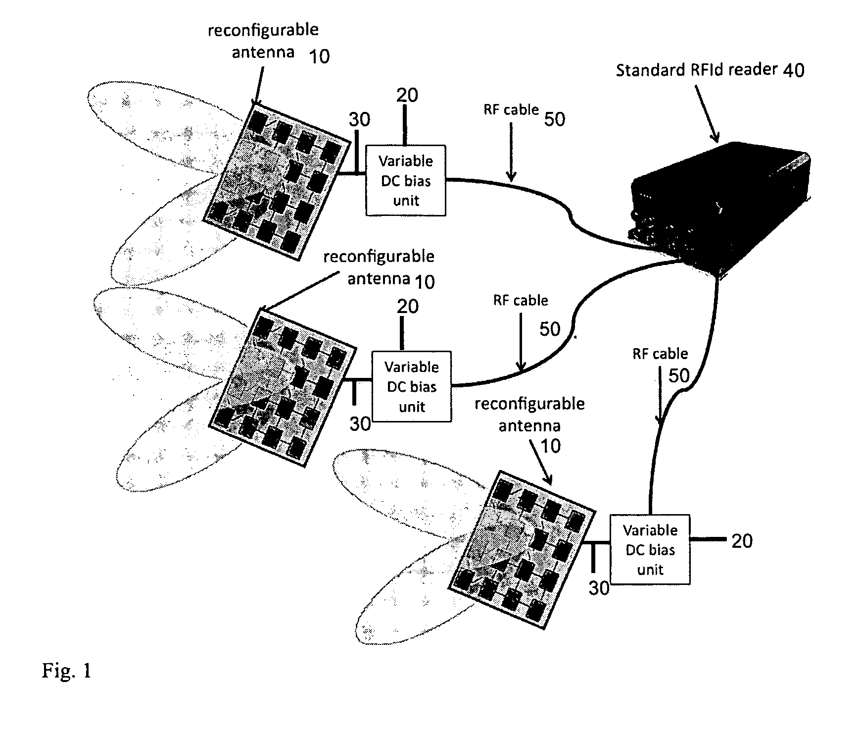
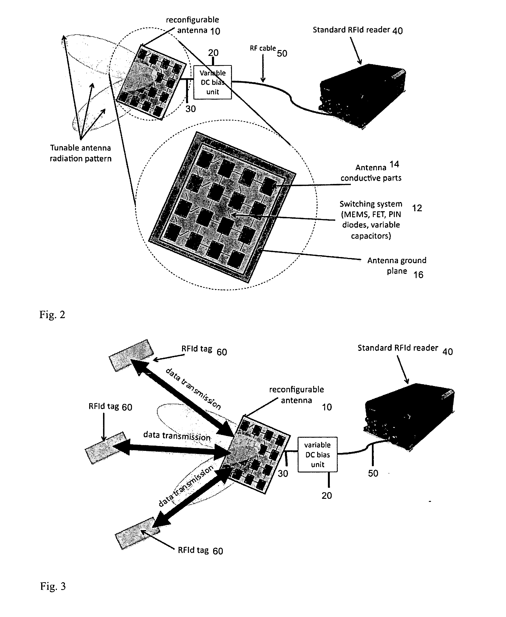
[0023]Current antenna solutions employed with RFId readers are not reconfigurable and typically radiate the energy statically with radiation patterns with fixed shape and polarization. In case of high tag density or when tags are used with non-compliant RFId materials (e.g. liquid, metal) or when they are applied on goods that can not be moved, it is difficult to properly expose the transponder to the radiated electromagnetic field with standard RFId antenna systems. In accordance with the invention, it is desired to dynamically change the direction in which the energy is radiated or the polarization of the radiated field so that th...


PUM


Abstract

An antenna system that allows increasing the reading reliability of RFId systems by dynamically changing the shape or the polarization of the electromagnetic field radiated by the RPId reader. The system includes at least one reconfigurable antenna, a variable DC bias unit and a methodology to efficiently use the system in RFId applications. The system allows changing the direction in which the energy is radiated or the polarization of the radiated field in order to “move” the electromagnetic field and to also read RFid tags that receive faint signals with standard RFid systems. Polarization alignment between the reader's antenna and the transponder allows for maximum power transfer, while changing the direction of radiation allows concentrating the electromagnetic field towards the transponder.

Description

CROSS REFERENCE TO RELATED APPLICATIONS[0001]This application claims benefit of U.S. Provisional Application No. 61 / 286,786 filed Dec. 16, 2009.TECHNICAL FIELD[0002]The present invention relates generally to the field of RFId antenna systems. Specifically, the present invention relates to an antenna system that can be used to improve the reading reliability of RFId systems.BACKGROUND OF THE INVENTION[0003]Radio-frequency identification (RFId) is an automatic identification method, relying on storing and remotely retrieving data using devices called RFId tags or transponders. The technology requires some extent of cooperation of an RFId reader and an RFId tag. The reading reliability of an RFId system depends mainly on the proper exposure of the RFId tag to the electromagnetic field radiated by the antenna reader. Once the transponder is exposed to the electromagnetic filed radiated by the reader, it collects the necessary power for activation and for sending a response signal to the...

Claims


Application Information

Patent Timeline
Patent Type & Authority Applications(United States)
IPC IPC(8): G06K7/01H01Q3/24
CPCH01Q3/00H01Q13/28H01Q15/0006H01Q11/02H01Q1/2216H01Q3/01H01Q23/00
Inventor PIAZZA, DANIELED'AMICO, MICHELE
Owner GPI SPA
Why Eureka
Try Eureka