Tuning-fork type quartz-crystal vibrating pieces and piezoelectric devices having low crystal impedance

a quartz crystal and vibrating piece technology, applied in piezoelectric/electrostrictive device details, piezoelectric/electrostrictive/magnetostrictive devices, piezoelectric/electrostriction/magnetostriction machines, etc., can solve the problem of increasing the probability of electrical shorts occurring between these structures, increasing the difficulty of adjusting the vibration frequency to a desired vibration frequency, and undesired increases in the ci of the piezo

Active Publication Date: 2012-10-04
NIHON DEMPA KOGYO CO LTD
View PDF8 Cites 18 Cited by
  • Summary
  • Abstract
  • Description
  • Claims
  • Application Information

AI Technical Summary

Benefits of technology

[0005]The present invention provides, inter alia, tuning-fork type quartz-crystal vibrating pieces, and piezoelectric devices comprising same, of which the vibration frequency can be easily adjusted without increasing CI.

Problems solved by technology

As the vibration frequency sensitivity increases, adjusting the vibration frequency to a desired vibration frequency, (32.768 kHz, for example) is increasingly difficult.
Also, as the device is miniaturized, the distance between metal film and excitation electrodes, both situated on the vibrating arms, becomes smaller, which increases the probability of electrical shorts occurring between these structures due to deposition of metal particles.
Unfortunately, these actions have resulted in undesired increases in the CI of the piezoelectric devices.

Method used


Image

  • Tuning-fork type quartz-crystal vibrating pieces and piezoelectric devices having low crystal impedance
  • Tuning-fork type quartz-crystal vibrating pieces and piezoelectric devices having low crystal impedance
  • Tuning-fork type quartz-crystal vibrating pieces and piezoelectric devices having low crystal impedance

Examples


first embodiment

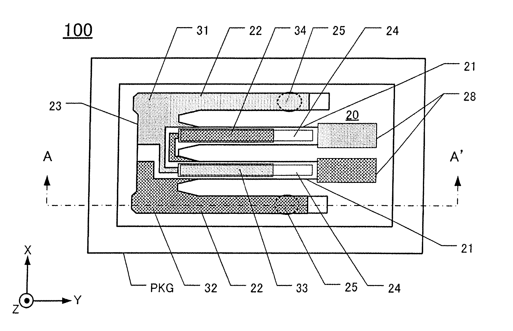
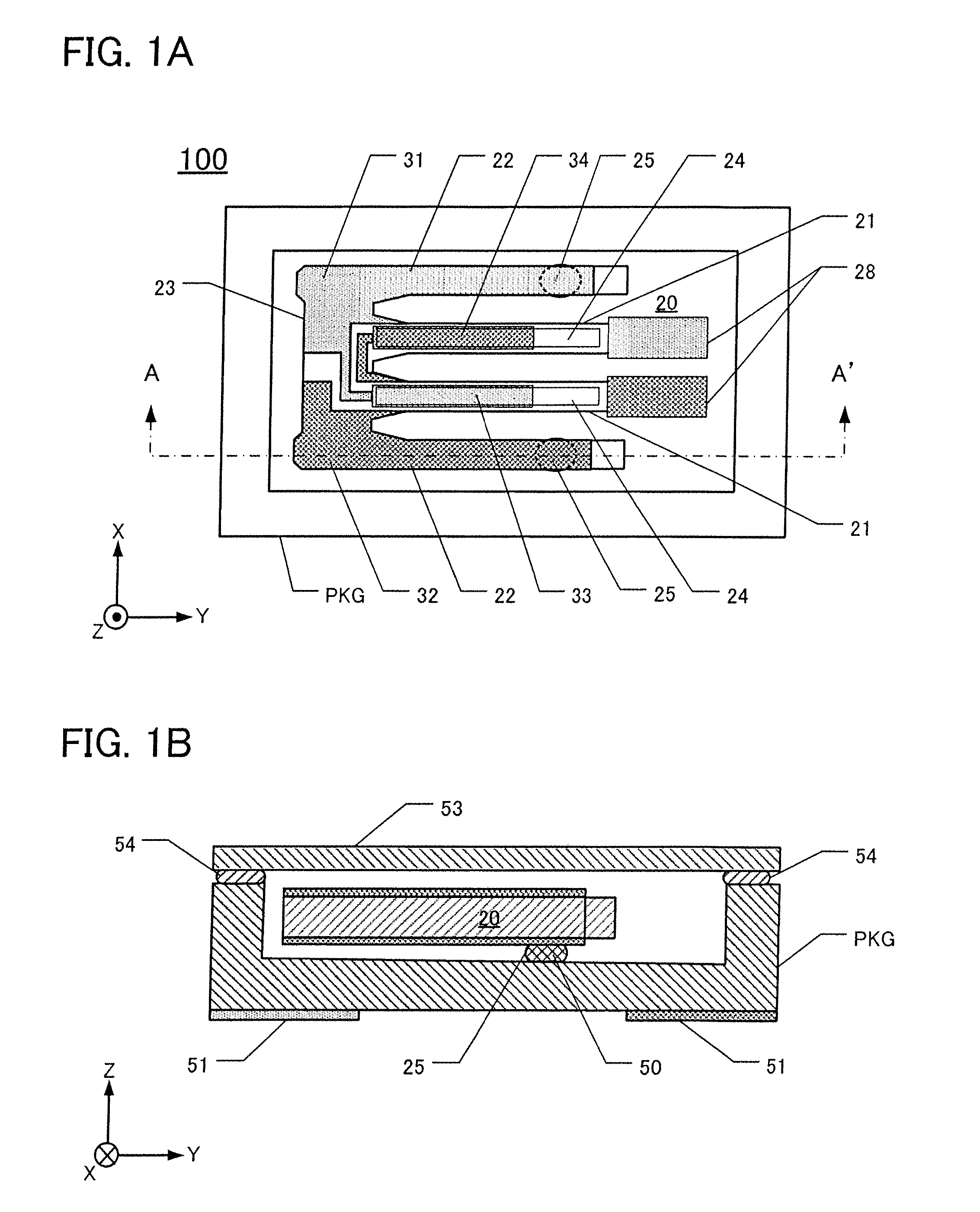
[0031]FIG. 1A is a plan view of a quartz-crystal device 100 according to this embodiment, in which the lid 53 has been removed to reveal underlying detail. FIG. 1B is a cross-section along the line A-A′ in FIG. 1A.

[0032]The quartz-crystal device 100 comprises a package lid 53, a package PKG, and a first embodiment of a tuning-fork type quartz-crystal vibrating piece 20. The vibrating piece 20 is contained in a vacuum in a recess defined in the package PKG. The lid 53 and package PKG are sealed together under vacuum using a sealing material 54. By fabricating the package lid 53 of borosilicate glass, vibration frequency can be adjusted even after assembling the quartz-crystal device.

[0033]The package PKG is fabricated from a ceramic material, for example, formed by stacking multiple ceramic sheets in a box shape. External electrodes 51 are situated on the lower main surface of the package PKG. The package PKG is a surface-mountable (SMD) type.

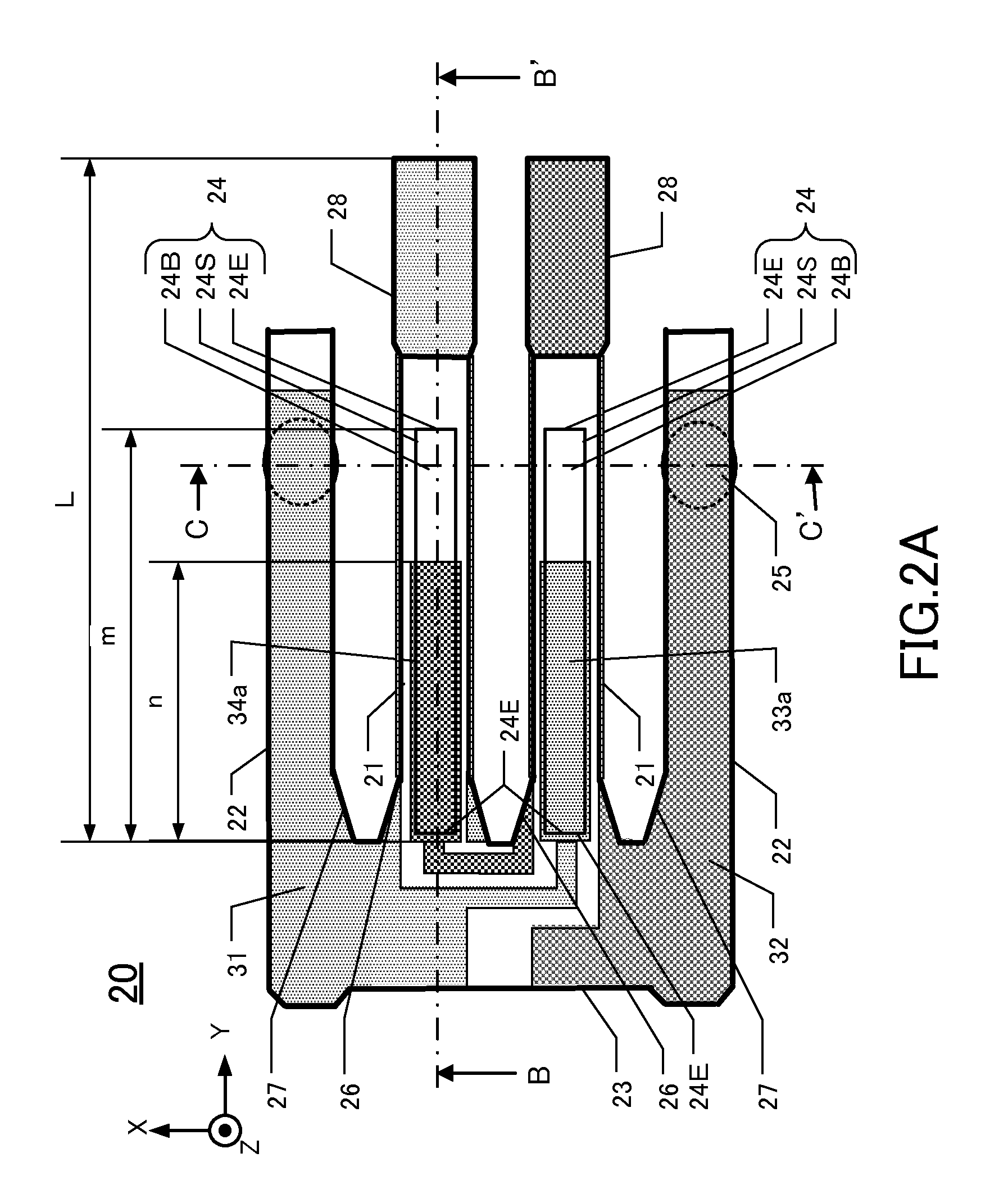
[0034]As shown in FIG. 1A, the first tuni...

second embodiment

[0068]FIG. 8A is a plan view of a second embodiment of a tuning-fork type quartz-crystal vibrating piece 20A, and FIG. 8B is a cross-section of the vibrating piece 20A along the line D-D′ in FIG. 8A. The shapes of the supporting arms 22′ and the base 23′ of the second embodiment of a vibrating piece 20A differ from corresponding shapes in the first embodiment 20. In FIG. 20A, the vibrating arms 21′ comprise respective constrictions 60 within the grooves 24. Other features of the second embodiment 20A are the same as in the first embodiment 20, and such similar features have the same respective reference numerals and are not described further below.

[0069]The vibrating piece 20A comprises a pair of vibrating arms 21′, a pair of supporting arms 22′, and a base 23′. The vibrating arms 21′ extend from the base 23′ in the Y′-axis direction. Respective grooves 24 are defined on each principal surface of the vibrating arms 21′. In each groove 24, respective constrictions 60 are formed that ...

third embodiment

[0076]FIG. 9A is a perspective view of a second embodiment of a quartz-crystal device 110, separated into individual pieces. FIG. 9B is a cross-section of the embodiment in FIG. 9A, along the line E-E′ in FIG. 9A. FIG. 10A is a plan view of a third embodiment of a tuning-fork type quartz-crystal vibrating piece 30, and FIG. 10B is a cross-section of the embodiment of FIG. 10A along the line F-F′.

[0077]The second embodiment of a quartz-crystal device 110 comprises the third embodiment of a vibrating piece 30. The difference between the third embodiment of a vibrating piece 30 and the first embodiment of a vibrating piece 20 is the presence in the third embodiment of a tuning-fork type quartz-crystal vibrating piece 30. This embodiment comprises an outer frame that surrounds the base and vibrating arms. Other features of the third embodiment are similar to corresponding features of the first embodiment 20 and are not described further below.

[0078]As shown in FIGS. 9A and 9B, the secon...


PUM


Abstract

Tuning-fork type quartz-crystal vibrating pieces are disclosed, of which the vibration frequency can be adjusted without increasing CI. An exemplary piezoelectric device has a pair of vibrating arms extending in a predetermined direction from a first edge of a base. Respective first grooves are defined in a first principal surface of the vibrating arms. The first grooves extend in the predetermined direction, and have first excitation electrodes extending from a back-edge surface but not completely to a front-edge surface of the grooves. Respective second grooves are defined in a second principal surface, opposite the first principal surface, of the vibrating arms. The second grooves extend in the predetermined direction, and have second excitation electrodes extending from a back-edge surface completely to a front-edge surface of the second grooves.

Description

CROSS-REFERENCE TO RELATED APPLICATIONS[0001]This application claims priority to and the benefit of Japan Patent Application No. 2011-072755, filed on Mar. 29, 2011, and Japan Patent Application No. 2012-005434, filed on Jan. 13, 2012, in the Japan Patent Office, the disclosures of which are incorporated herein by reference in their respective entireties.FIELD[0002]The present invention relates to, inter alia, tuning-fork type piezoelectric vibrating pieces fabricated from piezoelectric substrates, such as quartz-crystal, and having a pair of vibrating arms. The present invention also relates to piezoelectric devices comprising such tuning-fork type piezoelectric vibrating pieces.DESCRIPTION OF THE RELATED ART[0003]In recent years, as electronic devices have become smaller and thinner, smaller and thinner piezoelectric devices are demanded. Also demanded are piezoelectric devices exhibiting low crystal impedance values (CI-values), high quality, and stability. As tuning-fork type pi...

Claims


Application Information

Patent Timeline
Patent Type & Authority Applications(United States)
IPC IPC(8): H01L41/053H01L41/04H01L41/22H01L41/29
CPCH03H9/0595H03H9/21H03H9/1035
Inventor KAWANISHI, SHINGO
Owner NIHON DEMPA KOGYO CO LTD
Why Eureka
Try Eureka