
Charge/discharge determining apparatus and computer-readable medium

a technology of determining apparatus and computer-readable medium, which is applied in the direction of secondary cell servicing/maintenance, electrochemical generators, greenhouse gas reduction, etc., can solve the problems of power failure, power failure or the like, and it may take a certain time to issue a rotation chang

Active Publication Date: 2012-10-04
KK TOSHIBA
View PDF7 Cites 51 Cited by
  • Summary
  • Abstract
  • Description
  • Claims
  • Application Information

AI Technical Summary

Benefits of technology

The patent describes a system and method for managing a power generation facility and a battery system in an electrical power system. The system includes a system information acquiring section to gather information about the natural energy power supply and the battery system, a battery information acquiring section to gather information about the battery's charge / discharge capabilities, and a determining section to decide which battery to charge / discharge based on the available power supply. The system can compensate for changes in power supply by adjusting the rotation speed of the turbine in the power plant. The technical effect of this invention is to improve the stability of the power network and prevent power failures caused by natural energy power fluctuations.

Problems solved by technology

However, it takes a certain time from issuance of a rotation change command to establishment of a new turbine rotation speed.
The actual power supply amount is smaller than the planned value during such a transition period, possibly leading to a power failure.
That is, even if switching is made to a battery system, a power failure or the like may still occur.
Thus, the power network remains unstable.

Method used


Image

  • Charge/discharge determining apparatus and computer-readable medium
  • Charge/discharge determining apparatus and computer-readable medium
  • Charge/discharge determining apparatus and computer-readable medium

Examples


embodiment 1

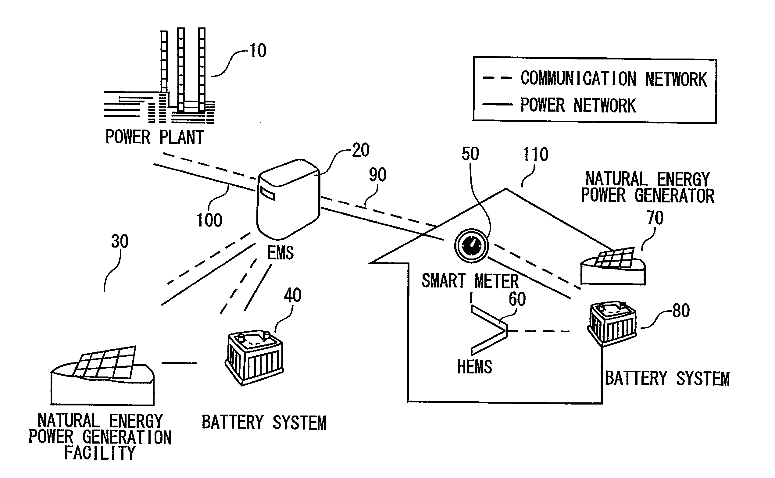
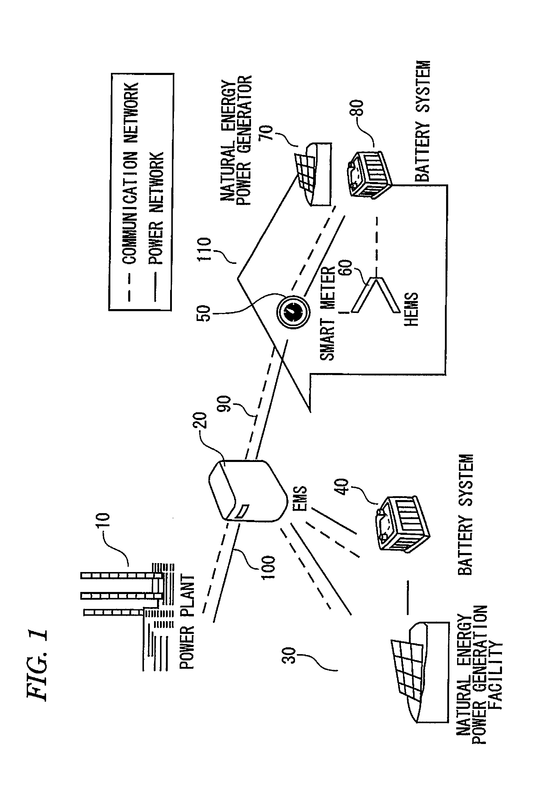
[0037]FIG. 1 shows a system according to a first embodiment of the invention.

[0038]The system according to the first embodiment includes a power plant (power supply command center) 10, an EMS (energy management system) 20, a natural energy power generation facility 30, a battery system 40, and a house 110. The house is equipped with a smart meter 50, an HEM (home energy management system) 60, a natural energy power generator 70, and a battery system 80.

[0039]The power plant 10, the EMS 20, the natural energy power generation facility 30, the battery system 40, and the home 110 are connected to each other by a power network 100 and a communication network 90.

[0040]In the house 110, the smart meter 50, the HEM 60, the natural energy power generator 70, and the battery system 80 are connected to each other by an intra-house part of the power network 100 and an intra-house part of the communication network 90.

[0041]The power plant (power supply command center) 10 generates power through...

embodiment 2

[0152]A system according to a second embodiment is similar to the system according to the first embodiment shown in FIG. 1 or 3. The configurations of a charge / discharge determining apparatus 200A and a charge / discharge controller 420A are similar to those of the charge / discharge determining apparatus 200 (see FIG. 10) and the charge / discharge controller 420 (see FIG. 13) according to the first embodiment.

[0153]The charge / discharge determining apparatus 200A and the charge / discharge controller 420A according to the second embodiment are different in part of the functions from the charge / discharge determining apparatus 200 and the charge / discharge controller 420 according to the first embodiment. The different functions will mainly be described below.

[0154]The charge / discharge determining apparatus 200A (EMS 20A) according to the second embodiment selects a battery system 40 to perform discharging or charging taking into consideration battery lifetimes of the respective battery syste...

embodiment 3

[0173]A system according to a third embodiment is similar to the system according to the first embodiment shown in FIG. 1 or 3. The configurations of a charge / discharge determining apparatus 200B and a charge / discharge controller 420B are similar to those of the charge / discharge determining apparatus 200 (see FIG. 10) and the charge / discharge controller 420 (see FIG. 13) according to the first embodiment.

[0174]The charge / discharge determining apparatus 200B and the charge / discharge controller 420B according to the third embodiment are different in part of the functions from the charge / discharge determining apparatus 200 and the charge / discharge controller 420 according to the first embodiment. The different functions will mainly be described below.

[0175]The charge / discharge determining apparatus 200B (EMS 20B) according to the third embodiment selects a battery system 40 to perform discharging or charging taking into consideration battery lifetimes of the respective battery systems ...


PUM

PropertyMeasurementUnit
electric energyaaaaaaaaaa
charge/discharge electric energiesaaaaaaaaaa
energyaaaaaaaaaa

Abstract

There is provided a charge / discharge determining apparatus for managing a natural energy power generation facility, a power plant and a plurality of batteries in an electrical power system. The apparatus includes: a system information acquiring section configured to acquire an actual value of natural energy power that is supplied from the natural energy power generation facility to the electrical power system; a battery information acquiring section configured to acquire battery electric energy information from the respective batteries, wherein the battery electric energy information indicates charge / discharge electric energies of the respective batteries which can be discharged from or charged in the respective batteries; and a determining section configured to determine at least one battery to be charged / discharged from among the plurality of batteries, wherein when an absolute value of a difference between the actual value and a predicted value of the natural energy power is larger than a threshold value.

Description

[0001]This application claims priority from Japanese Patent Application No. 2011-069145, filed on Mar. 28, 2011, the entire contents of which are hereby incorporated by reference.BACKGROUND[0002]1. Field[0003]Embodiments described herein relate to a charge / discharge determining apparatus and computer-readable medium.[0004]2. Description of the Related Art[0005]In recent years, various kinds of natural energy have come to serve as major power supply sources like power plants.[0006]However, the output power of natural energy varies to a large extent. For example, the generated power is very low when the weather is bad (in the case of photovoltaic power generation) or when no wind blows (in the case of wind power generation). When the power supplied from natural energy power supply sources drops rapidly, the actual power supply amount of a power network becomes much smaller than a planned value.[0007]In such a case, to increase the actual power supply amount to the planned value, it is...

Claims


Application Information

Patent Timeline
Patent Type & Authority Applications(United States)
IPC IPC(8): H01M10/46
CPCH01M10/482H02J3/32H02J3/383H02J3/46H02J13/0055Y02E40/72Y02E10/566Y04S10/123Y04S10/14Y02E60/722Y02E70/30Y02E10/563H02J13/00012H02J2300/24H02J3/381H02J13/00017Y02E10/56Y02E40/70Y02E60/00Y04S40/124Y02E60/10
Inventor NISHIBAYASHI, YASUYUKIISE, KOTAROTERAMOTO, KEIICHIWADA, TAKAHISA
Owner KK TOSHIBA
Learn More