Controlling an inverter device of a high voltage DC system for supporting an ac system

a high-voltage dc system and control device technology, applied in the direction of dc-ac conversion without reversal, process and machine control, instruments, etc., can solve the problems of increasing the overall cost of installed equipment, voltage/power stability, and inability of the connected power system to provide, so as to increase the transient mechanical and voltage stability of the combined ac

Active Publication Date: 2012-10-04
HITACHI ENERGY SWITZERLAND AG
View PDF3 Cites 33 Cited by
  • Summary
  • Abstract
  • Description
  • Claims
  • Application Information

AI Technical Summary

Benefits of technology

[0023]The invention has a number of advantages. It can be be combined with a weak AC system. Through emulating a voltage source converter according to the principles of the invention it is possible to generate reactive power to and absorb reactive power from an AC system, which increases the transient mechanical and voltage stability of the combined AC and DC systems.

Problems solved by technology

All these factors influence the system performance, and to mitigate their effects it might be necessary to install additional equipment like static or synchronous compensators, which increases the overall cost of the installed equipment.
The Voltage / Power stability is a basic issue of concern when HVDC converters with line commutated converters are connected to a weak AC system.
The basic mechanism in unstable situations is the inability of the connected power system to provide the reactive power needed by the converter to maintain acceptable system voltage.
Alternatively, other operating properties can also be found like constant DC voltage or constant firing angle α. However, all these operating conditions imply similar limiting conditions in terms of strength of the connected AC system.

Method used


Image

  • Controlling an inverter device of a high voltage DC system for supporting an ac system
  • Controlling an inverter device of a high voltage DC system for supporting an ac system
  • Controlling an inverter device of a high voltage DC system for supporting an ac system

Examples


first embodiment

[0107]Dynamically the CCA unit 32 may have a proportional branch in parallel with an integrating branch. The integrator in the CCA unit has a maximum and minimum internal limitation. The maximum limitation depends on the mode and conditions of operation of the converter. The generation of maximum limitation signal is produced by external functions to the CCA unit 32, and here by the AC voltage controller 36 and / or the α-max controller 44. This signal is obtained from the second combining unit 42, which in the inventions selects the signal having the lowest value of the signals supplied by the AC voltage controller 36 and α-Max controller 44 to be used as maximum firing angle, which are described below.

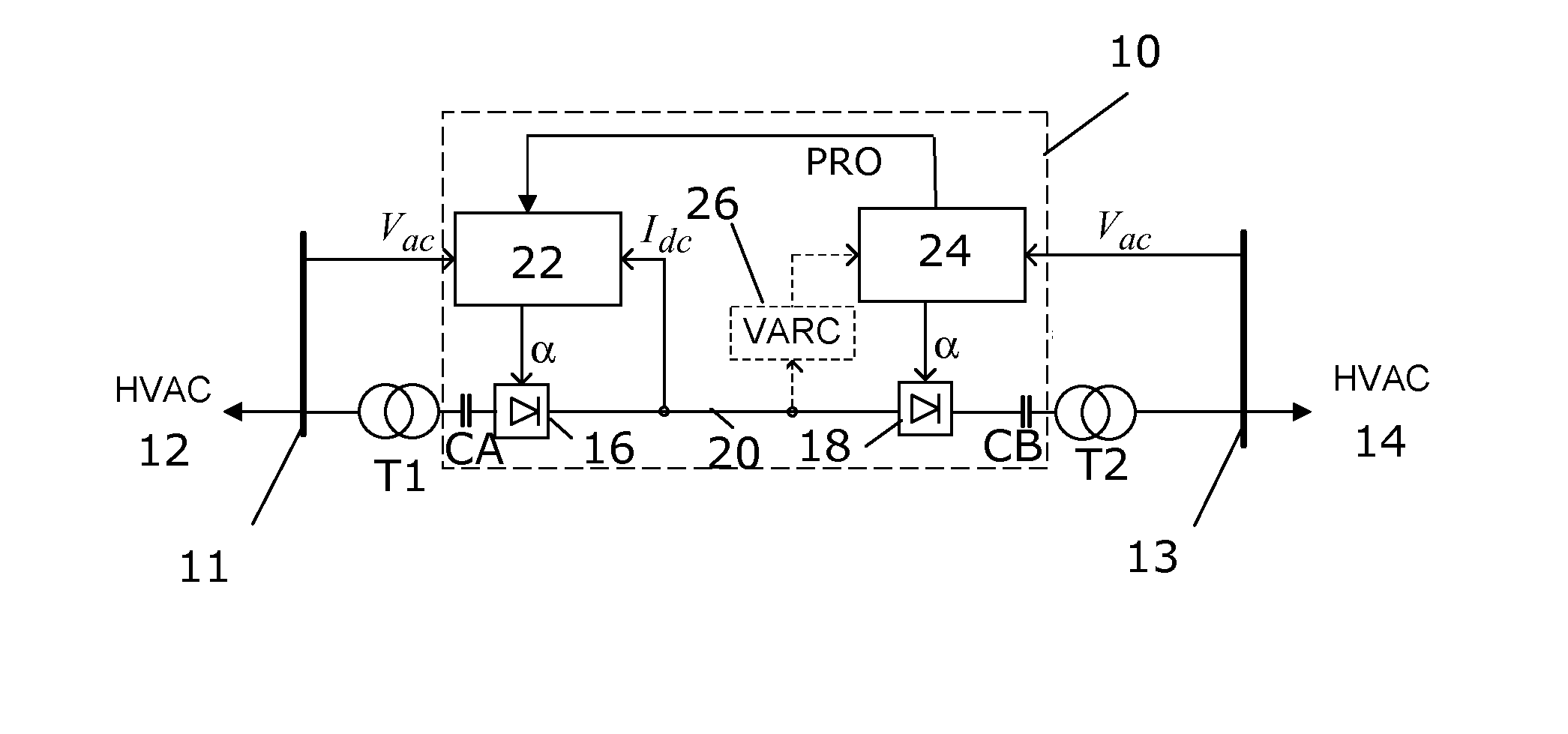
[0108]The AC Voltage controller 36 is the central element for operation according to the invention. Under normal operation, the inverter converter 18 will control the AC voltage at the filter bus 13, while injecting the active power that is controlled by the rectifier converters 16.

[01...

second embodiment

[0135]In the invention the control loop of the controller is basically an ordinary PI regulator having the AC voltage measured at the converter filter bus as a main control variable. The firing angle of the inverter is then determined from

α=180°-αMAX_UAC+dαMAX_CCCwhere(9)dαMAX_CCC=k0+k1dxcidudio+k2(dxcidudio)2+kgp0+kgp1(γCalc′-γbase′)dxcidudio+kgp2[(γCalc′-γbase′)dxcidudio]2(10)

which also corresponds to the second contribution from the second α-max calculating element in the first embodiment. Here γCalc is the actual extinction value, the determination of which will be described later on.

[0136]FIG. 9 shows one variation of the PI control element 40 and gains control element 38 of the AC voltage controller together with the second combining unit 42.

[0137]The PI control element 40 here includes a fourth combining unit 66, which receives the measured voltage UAC, compares it with a voltage reference UAC—REF and supplies the difference to a first multiplying unit 68. The voltage referen...


PUM


Abstract

The invention concerns a method of controlling an inverter device, a control device as well as an inverter device and a direct current power transmission system. The direct current power transmission system is provided for connection to an AC voltage bus of an AC power system and comprises the control device and the inverter device that converts between DC power and AC power. The control device receives measurements of the voltage (VAC) at the AC voltage bus and controls the inverter device to provide a constant AC voltage on the bus.

Description

FIELD OF INVENTION[0001]The present invention generally relates to power transmission systems. More particularly the present invention relates to a method and control device for controlling an inverter device connected to an AC voltage bus of an AC power system, such an inverter device as well as to a direct current power transmission system.BACKGROUND[0002]The phenomena related with High Voltage Direct Current (HVDC) converter connected to weak AC network have been extensively studied. See for instance “Guide for planning DC links terminating at AC locations having Low Short-Circuit capacities”—Part I: AC / DC interaction phenomena', CIGRE working group 14.07, Report 68, June 1992 and “IEEE guide for planning DC links terminating at AC locations having Low Short-Circuit capacities”, IEEE Std 1204-1997[0003]These phenomena have different implications on the design of HVDC system. The following issues are of special concern:[0004]Risk for voltage / power instability[0005]High temporary o...

Claims


Application Information

Patent Timeline
Patent Type & Authority Applications(United States)
IPC IPC(8): H02M7/44H02J3/36
CPCH02J3/16H02J3/36Y02E60/60H02M7/7575Y02E40/34H02M7/525Y02E40/30H02M7/4803
Inventor FISCHER DE TOLEDO, PAULO
Owner HITACHI ENERGY SWITZERLAND AG
Why Eureka
Try Eureka