
Hearing device with reduced acoustic wind sensitivity

Inactive Publication Date: 2012-10-04
SIVANTOS PTE LTD
View PDF2 Cites 0 Cited by
  • Summary
  • Abstract
  • Description
  • Claims
  • Application Information

AI Technical Summary

Benefits of technology

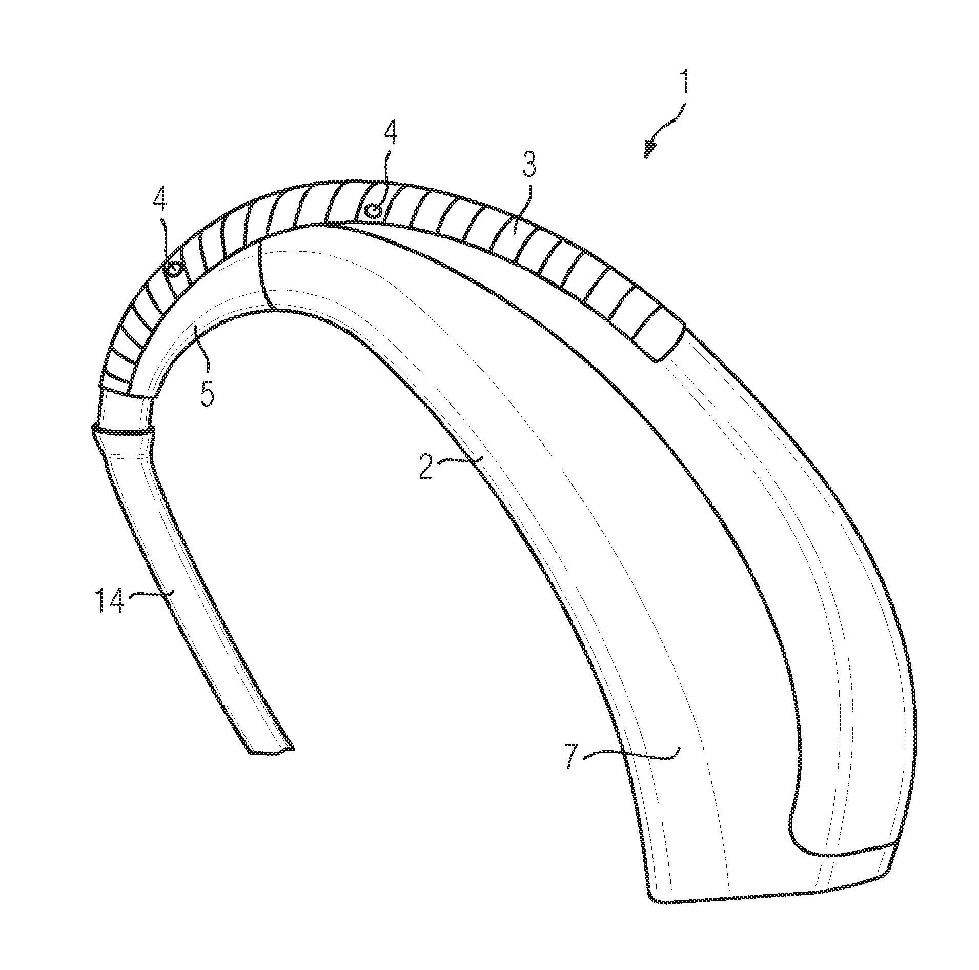
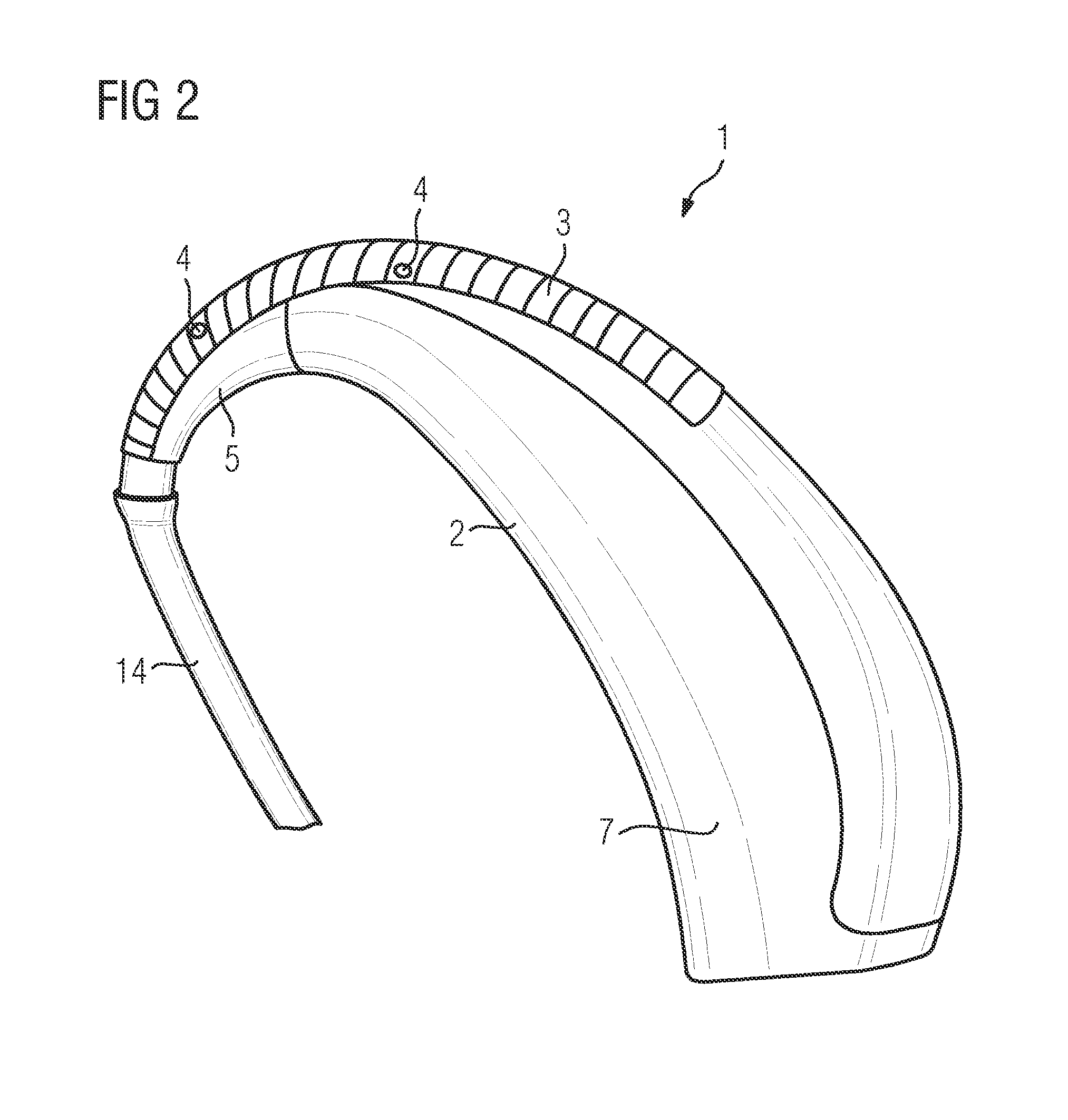
[0014]The best effect in terms of increasing the critical wind speed is generally then achieved if the longitudinal axis of the scales is parallel to the vector of the wind speed. In the event of a hearing device which is worn behind the ear of a hearing device wearer, wind, e.g. when walking, will blow past the hearing device predominantly in parallel with the auricle, i.e. in the straight line of sight of a hearing device wearer, so that an alignment of the longitudinal axis of the scales parallel to the straight line of sight of the hearing device wearer is advantageous. Since on account of the curved surface of a hearing device, not all longitudinal axes of the scales can be aligned in the straight line of sight of the hearing device wearer, at least one component is to be aligned in this direction.
[0019]This method is advantageous in that the shark skin structure can be applied to the hearing device with simple means, for example by means of adhesion.
[0021]Modern injection molding methods enable textures in the micrometer range, with which hearing device housings with a shark skin structure can be cost-effectively produced for instance with high quality. Further methods of impressing a shark skin structure into a hearing device housing or a hearing device hook are high-precision laser drilling methods. A hard or hardened surface lends itself to a stable surface structure, such as can be achieved for instance by means of glass fiber reinforcement.

Problems solved by technology

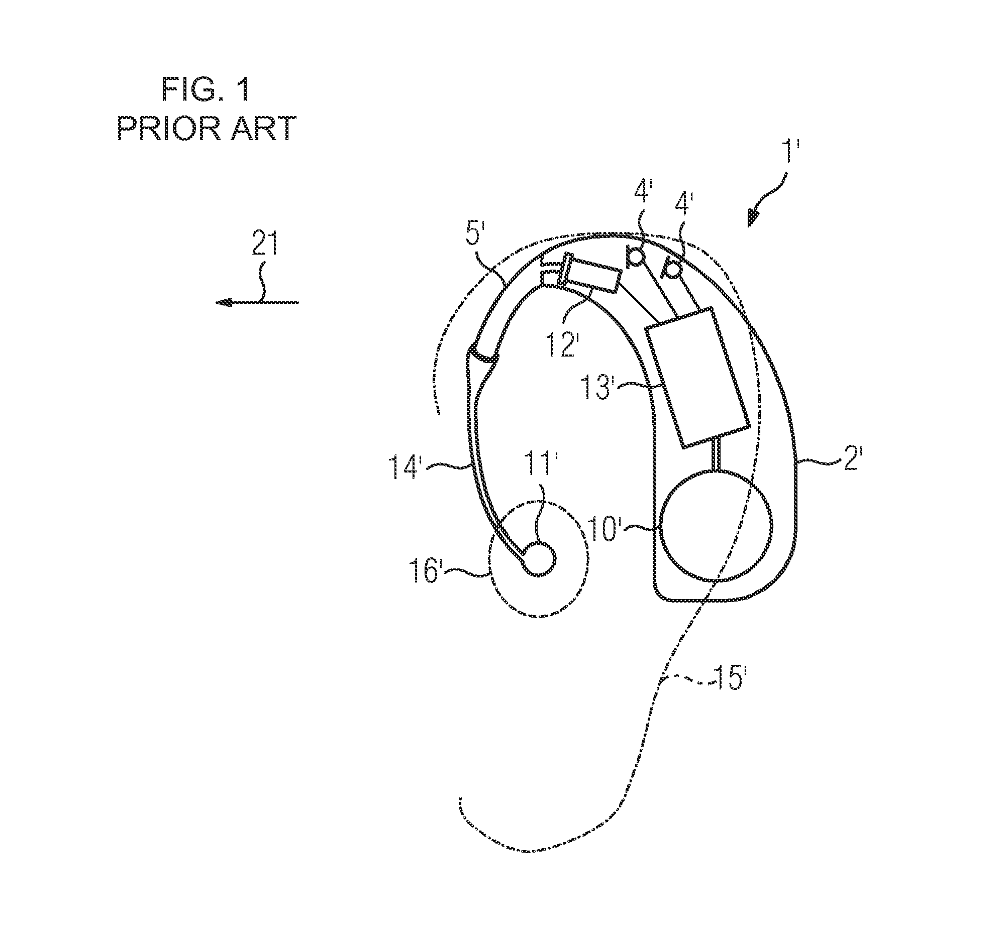
If this swirling appears in the region of the microphones and / or the microphone inlet openings of a hearing device, they produce noise which can be perceived as bothersome by a hearing device wearer, or the one possible wanted signal, i.e. speech, is overlayed and the perception of the wanted signal is negatively influenced.

Method used


Image

  • Hearing device with reduced acoustic wind sensitivity
  • Hearing device with reduced acoustic wind sensitivity
  • Hearing device with reduced acoustic wind sensitivity

Examples


Embodiment Construction

[0032]Referring now to the figures of the drawing in detail and first, particularly, to FIG. 1 thereof, there is shown a schematic representation of a behind-the-ear hearing device 1′ according to the prior art. The device has several functional parts, including a housing 2′ to be worn behind the auricle 15′ of a hearing device wearer. Aside from electronic components which are combined to form a signal processing unit 13′, two microphones with the microphone openings 4′, a battery 10′ and a receiver 12′ are arranged in the housing 2′. The acoustic signal generated by the receiver 12′ is guided through a hearing device hook 5′ and an acoustic tube 14′ to an earpiece 11′, which is inserted into an auditory canal 16′ of the hearing device wearer. When the hearing device is being worn, the straight line of sight of the hearing device wearer defines an axis 21, whereby the line of sight in FIG. 1 is also specified by an arrow.

[0033]FIG. 2 shows important parts of an inventive hearing de...


PUM


Abstract

A hearing device has reduced acoustic wind sensitivity. For that purpose, the hearing device has a surface formed with a shark skin structure.

Description

CROSS-REFERENCE TO RELATED APPLICATION[0001]This application claims the priority, under 35 U.S.C. §119, of German patent application DE 10 2011 006 563.6, filed Mar. 31, 2011; the prior application is herewith incorporated by reference in its entirety.BACKGROUND OF THE INVENTIONField of the Invention[0002]The present invention relates to a hearing device with reduced acoustic wind sensitivity.[0003]Hearing devices are used to supply hearing-impaired persons with acoustic ambient signals which are processed and amplified to compensate for and / or treat the respective hearing impairment. A hearing device includes in principle one or more input converters, a signal processing facility with an amplification facility and / or an amplifier and an output converter. The input converter is generally a receiving transducer, e.g. a microphone and / or an electromagnetic receiver, such as an induction coil. The output converter is generally implemented as an electroacoustic converter, e.g. miniatur...

Claims


Application Information

Patent Timeline
IPC IPC(8): H04R25/00
CPCH04R25/65H04R2410/07H04R2225/021H04R25/658H04R25/607
Inventor MEISTER, BERNDRITTER, HARTMUTWEISTENHOFER, CHRISTIAN
Owner SIVANTOS PTE LTD
Learn More