Image formation system, method for image formation and recording medium

a technology of image formation and recording medium, applied in the field of image formation system and recording medium, can solve problems such as the inability to maintain printing order, and achieve the effect of preventing wasteful use of printing paper

Inactive Publication Date: 2012-10-04
CANON KK
View PDF6 Cites 9 Cited by
  • Summary
  • Abstract
  • Description
  • Claims
  • Application Information

AI Technical Summary

Benefits of technology

[0012]However, in the present invention, when recovering from a jam, it is possible to suppress wasteful use of printing paper by using paper during reprinting without discarding paper that has been printed on and is backed up in a former stage and without changing the printing order.

Problems solved by technology

In a printing system that completes printing by physically connecting printers, when data that could not be printed properly due to a jam that occurred in the subsequent printer is reprinted after that jam has recovered, it was not possible to maintain the printing order.

Method used


Image

  • Image formation system, method for image formation and recording medium
  • Image formation system, method for image formation and recording medium
  • Image formation system, method for image formation and recording medium

Examples


embodiment 1

Explanation of the Overall Configuration

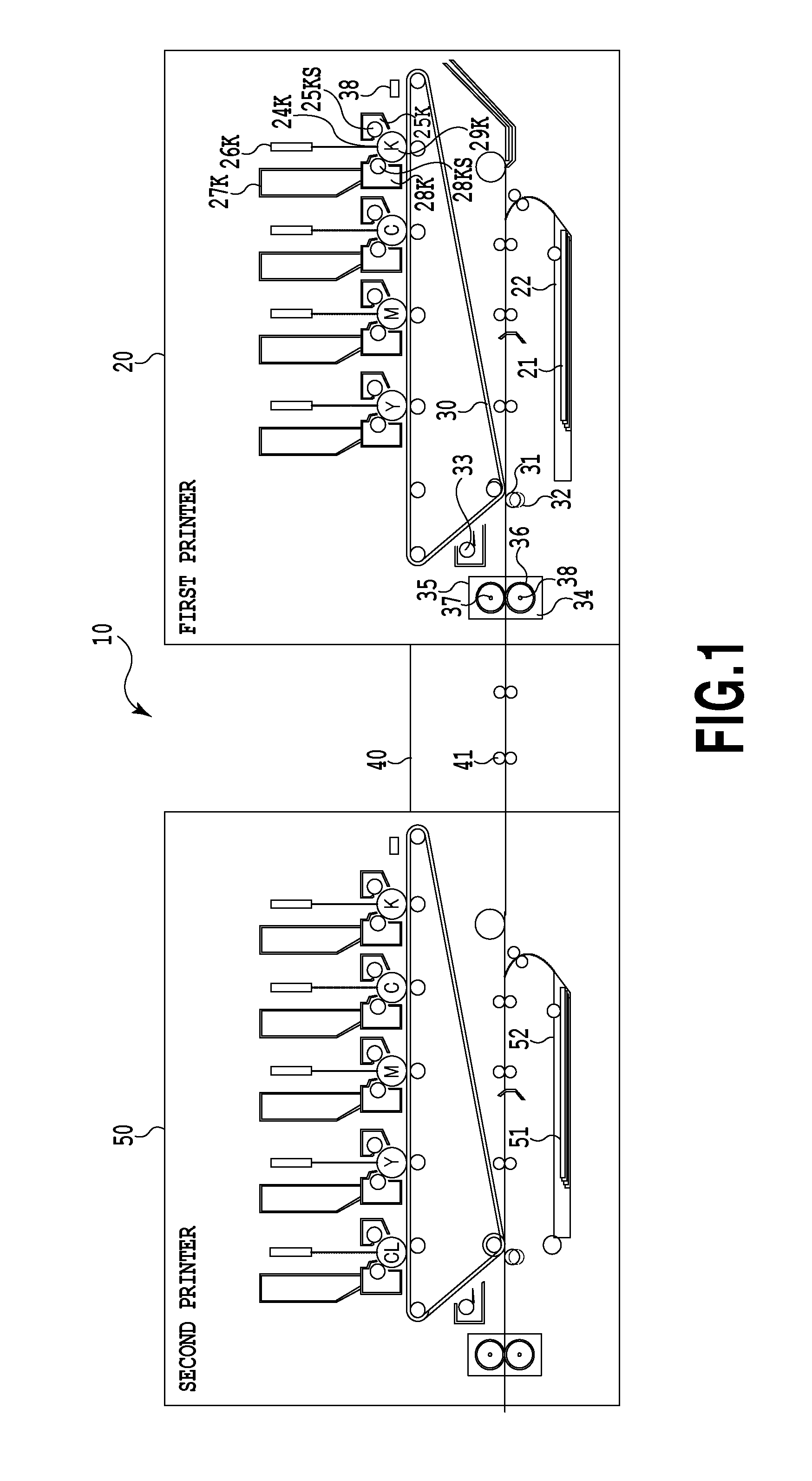
[0034]FIG. 1 is an image formation system of an embodiment of the present invention. FIG. 1 illustrates the overall configuration of a printing system 10. The printing system comprises a first printer 20 that first takes in paper 21, and a second printer 50 that receives the paper 21 that is fed from the first printer 20. An intermediate buffer 40 is located between the first and second printers. The intermediate buffer temporarily stores paper between the first and second printers. The first and second printers perform printing using a plurality of various kinds of toner; however, when the printing speeds between the two printers differs, this intermediate buffer 40 resolves the difference in printing speeds. Moreover, in this embodiment, the case is presumed wherein, when forming an image of inputted image data using a plurality of sheets of printing material, this printing material causes a jam.

[0035]Here, paper as the printing material, wh...

embodiment 2

[0091]In the first embodiment, as illustrated in FIG. 11, the operator is prompted to select either “Normal (Stable quality)” or “Paper priority (Cost priority)” as the recovery method when performing recovery by the second MFP 231, and recovery is performed based on the selection result. However, when a jam actually occurs and the discarded pages must be recovered, it is often difficult for the operator to determine whether priority should be given to the quality or to the cost. Therefore, in this embodiment, two modes have been provided to assist in determining whether to select “Normal (Stable quality)” or “Paper priority (Cost priority)”. In other words, as illustrated in FIG. 12, these two modes are the “Automatic” mode and “Test Printing” mode. The “Automatic” mode is a setting that automatically determines based on printing data and environmental information whether to select “Normal (Stable quality)” or “Paper priority (Cost priority)” of the first embodiment. On the other h...


PUM


Abstract

An image formation system wherein a paper discharge unit of a first image formation device which forms an image using a colored printing agent, is connected with a first paper feeder of a second image formation device which forms an image using a transparent printing agent, and a printing material formed by the first image formation device is fed to the second image formation device, the image a formation system comprising: a jam detector; and an image formation unit that, when detecting a jam in the second image formation device, causes a printing material to be fed to the second image formation device from a second paper feeder separate and causes the second image formation device to form an image upon detecting a jam in the second image formation device, and second image data inputted together with the first image data using colored and transparent printing agents.

Description

BACKGROUND OF THE INVENTION[0001]1. Field of the Invention[0002]The present invention relates to an image formation system, method for image formation and recording medium that executes the printing method, and particularly to an image formation system with a plurality of image formation devices, method for image formation and recording medium.[0003]2. Description of the Related Art[0004]Typically, a printing system that connects the paper discharge unit and paper feeders of a plurality of printers in order to complete one printing job is currently used for spot color printing and double-sided printing. In recent years, this kind of printing system is also used for special toner printing. For example, in a printing system wherein one printer transfers and fixes CMYK toner and clear toner, which is one kind of special toner, problems occur related to the amount of toner used. More specifically, in an image processor, there is a limit to the amount of toner that can be fixed at one ti...

Claims


Application Information

Patent Timeline
Patent Type & Authority Applications(United States)
IPC IPC(8): G03G13/00G03G15/00
CPCG03G2215/00021G03G15/502G03G21/1604G03G15/70G03G15/6529
Inventor SHINDO, YUKIHIRO
Owner CANON KK
Why Eureka
Try Eureka