Tissue Sampling Device And Method

a tissue sampling and tissue technology, applied in medical science, surgery, vaccination/ovulation diagnostics, etc., can solve the problems of high cost, complex and complicated of many devices, while sophisticated

Active Publication Date: 2012-10-04
COOK MEDICAL TECH LLC
View PDF3 Cites 50 Cited by
  • Summary
  • Abstract
  • Description
  • Claims
  • Application Information

AI Technical Summary

Problems solved by technology

Many devices, while sophisticated, are costly and complex.
Other problems with conventional technology relate to trauma experienced by the patient, or only narrow practicable use of certain devices with respect to tissue type or sample size.

Method used


Image

  • Tissue Sampling Device And Method
  • Tissue Sampling Device And Method
  • Tissue Sampling Device And Method

Examples


Embodiment Construction

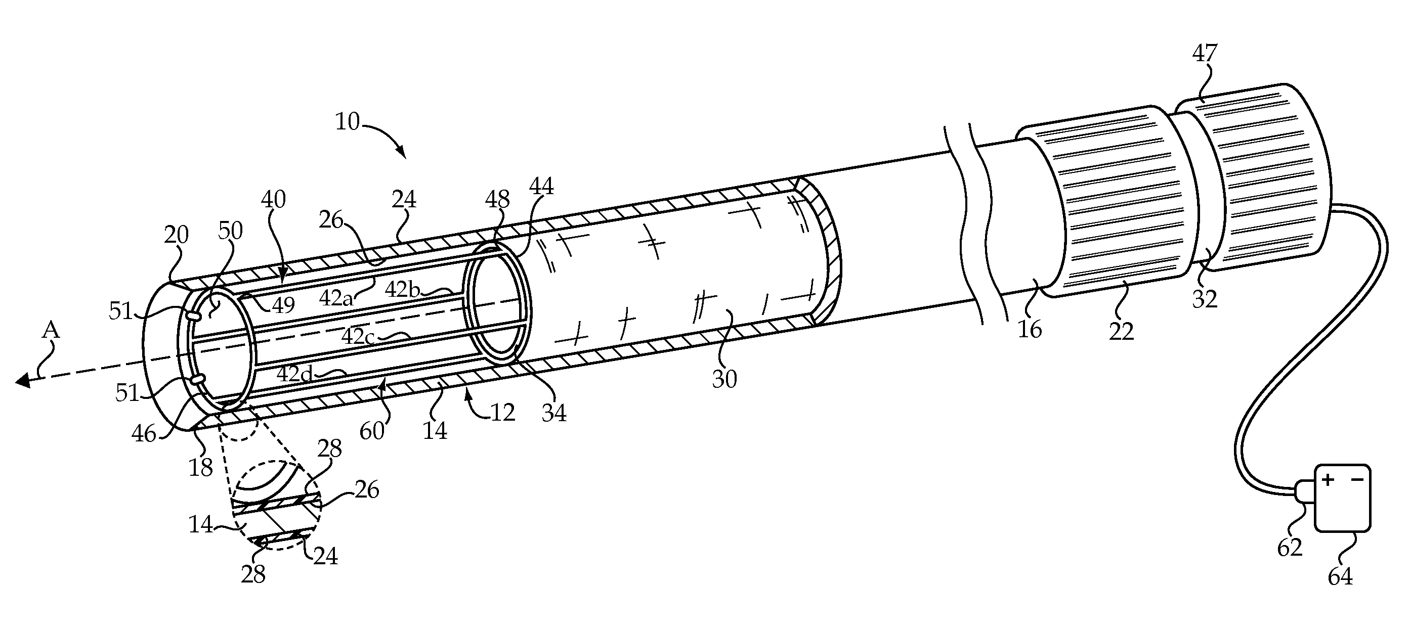
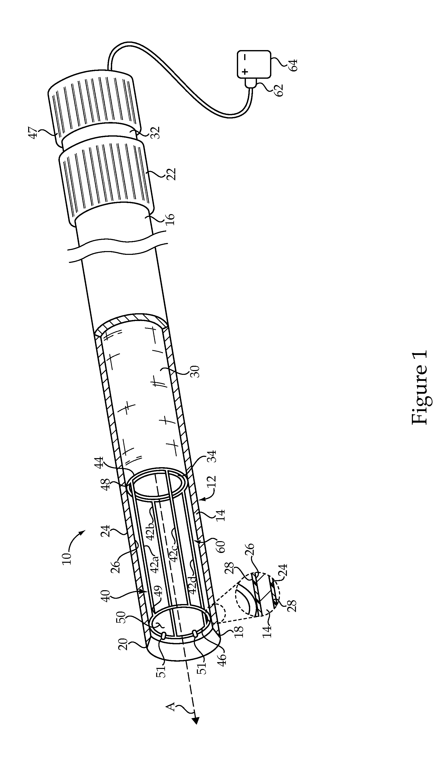
[0017]Referring to FIG. 1, there is shown a tissue sampling device 10 according to one embodiment. Device 10 may include a cannula 12 having an elongate tubular body 14 defining a longitudinal axis A extending between a proximal cannula end 16 and a distal cannula end 18. A handle 22 may be coupled with proximal cannula end 16. Distal cannula end 18 may include a sharpened coring tip 20. An elongate shaft 30 is positioned within cannula 12 and may be oriented coaxially with elongate tubular body 14. Shaft 30 may include a proximal shaft end 32 having a handle 47 coupled therewith, and a distal shaft end 34 positioned such that it is recessed within elongate tubular body 14 from tip 20. A cavity 50 extends between sharpened coring tip 20 and distal shaft end 34.

[0018]A cutting mechanism or “cutter”40 having an axially advancing orientation is positioned within cannula 12, and extends between distal shaft end 34 and tip 20. Cutter 40 may include a plurality of axially advancing cuttin...


PUM


Abstract

A tissue sampling device includes a cannula having an elongate tubular body with a sharpened coring tip. A shaft extends within the cannula and is coupled with a cutter having an axially advancing wire extending between a distal end of the shaft and the sharpened coring tip. The axially advancing wire is movable in a cutting path defining an arc about the longitudinal axis, by way of rotating the shaft relative to the cannula.

Description

RELATION TO OTHER PATENT APPLICATION[0001]This application claims priority to provisional patent application 61 / 470,692, filed Apr. 1, 2011 with the same title.TECHNICAL FIELD[0002]The present disclosure relates generally to devices and methods for obtaining tissue samples for biopsy, and relates more particularly to a tissue sampling device in which a cutter having an axially advancing orientation sweeps an arcing cutting path through body tissue received within a cannula.BACKGROUND[0003]Acquiring samples of human body tissue for biopsy purposes is performed with a wide variety of devices and methodologies. In many cases, the type of tissue to be sampled can influence the selection of appropriate tools. For instance, tissue sampling mechanisms used for sampling bone marrow may be quite different from those used in obtaining samples of tissue from the esophagus, or those used to obtain samples from certain internal organs.[0004]While certain tissues can be sampled with a simple need...

Claims


Application Information

Patent Timeline
Patent Type & Authority Applications(United States)
IPC IPC(8): A61B10/02
CPCA61B10/0266A61B18/082A61B17/32056A61B17/32053
Inventor CAGE, LOGAN
Owner COOK MEDICAL TECH LLC
Why Eureka
Try Eureka