Pretensioner, seatbelt retractor including the pretensioner, and seatbelt apparatus including the seatbelt retractor

a technology of seatbelt retractor and pretensioner, which is applied in the direction of belt retractor, vehicle safety belt, belt retraction, etc., can solve the problems of increasing the size of the pretensioner, increasing the size of the seatbelt retractor, and relatively large number of balls, etc., and achieves the effect of not easy to set, simplified stopper structure, and reduced force transmission

Inactive Publication Date: 2012-10-11
JOYSON SAFETY SYST JAPAN KK
View PDF5 Cites 11 Cited by
  • Summary
  • Abstract
  • Description
  • Claims
  • Application Information

AI Technical Summary

Benefits of technology

[0022]According to the pretensioner and the seatbelt retractor of the present invention having these features, when the ring gear rotates by a predetermined rotation amount in the seatbelt retracting direction, the stopper provided in the ring gear comes into contact with the opposing force transmission member or pipe. This contact of the stopper with the force transmission member or the pipe can effectively stop the rotation of the ring gear.
[0023]Since the stopper provided in the ring gear directly presses the force transmission member or the pipe, it is unnecessary to connect a pair of force transmission members by a connecting member such as a bridge, unlike the above-described example of the pretensioner described in PTL 2. Therefore, a connecting structure for the pair of force transmission members can be eliminated. Thus, a stopper structure including the stopper and the force transmission member is simplified, and the stopper structure does not need to be large. As a result, the stopper structure formed by the stopper, and the force transmission member or the pipe can be easily set in a limited space in the case body. This can suppress the increase in cost of the pretensioner.
[0024]Since it is unnecessary to connect the pair of force transmission members by the connecting member such as a bridge, all force transmission members can b

Problems solved by technology

When the ball storage chamber is thus provided, the size of the pretensioner is increased, and the size of the seatbelt retractor is inevitably increased.
Since the balls are stored in the ball storage chamber, the number of balls is relatively large, and the length of the expensive pipe is lar

Method used


Image

  • Pretensioner, seatbelt retractor including the pretensioner, and seatbelt apparatus including the seatbelt retractor
  • Pretensioner, seatbelt retractor including the pretensioner, and seatbelt apparatus including the seatbelt retractor
  • Pretensioner, seatbelt retractor including the pretensioner, and seatbelt apparatus including the seatbelt retractor

Examples


first embodiment

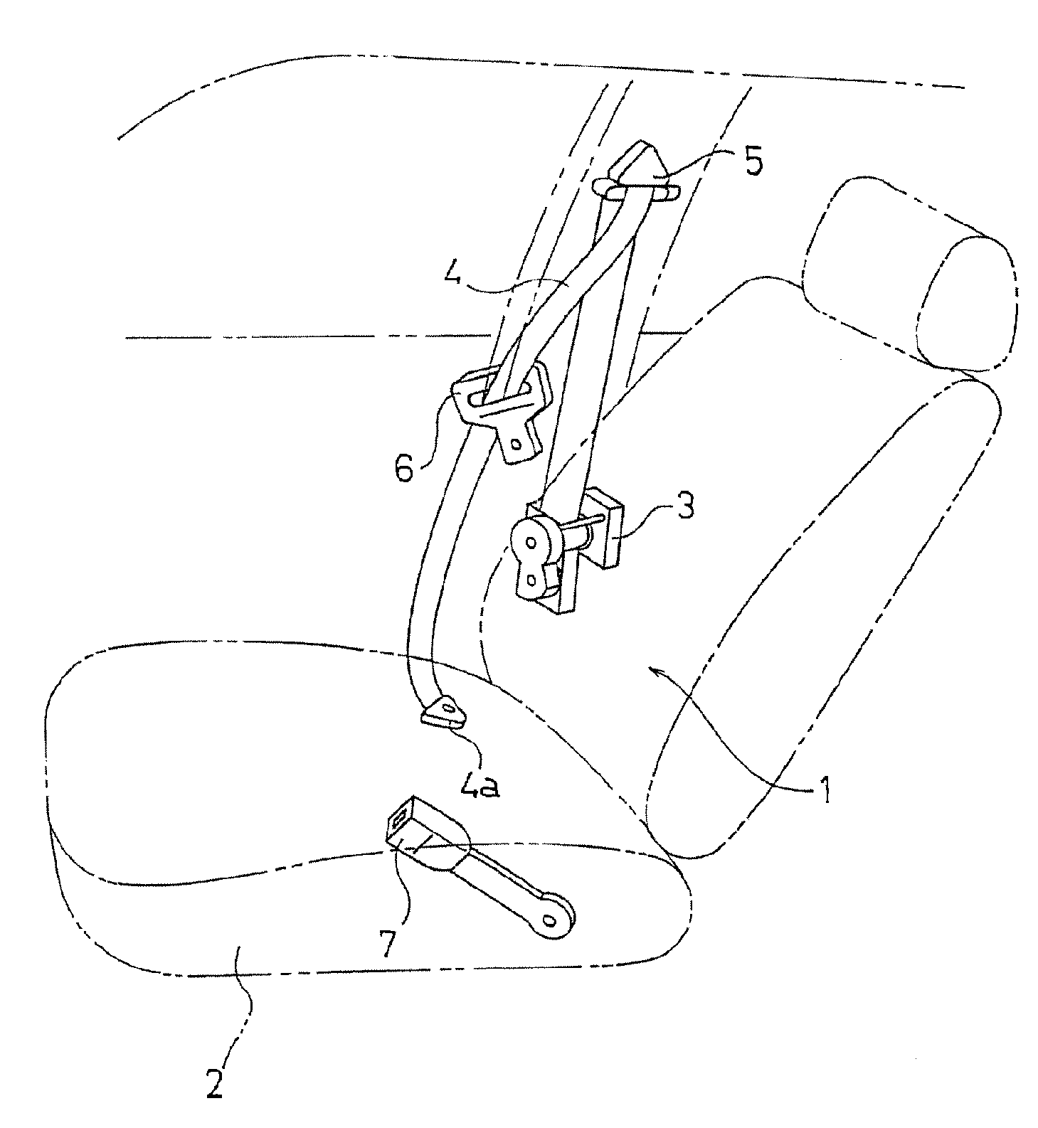
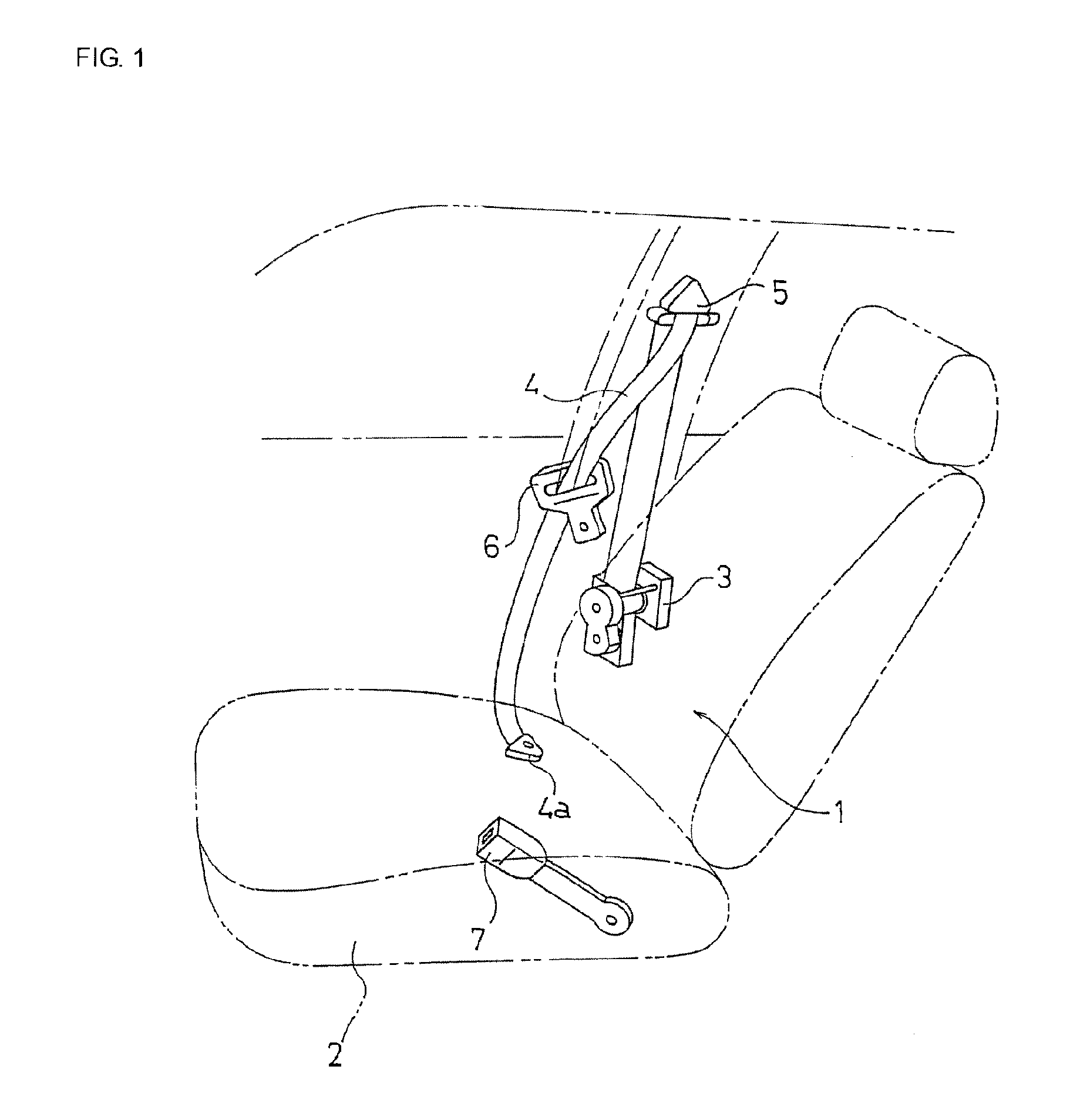
[0047]FIG. 1 schematically illustrates a seatbelt apparatus including a seatbelt retractor according to the present invention.

[0048]As illustrated in FIG. 1, a seatbelt apparatus 1 of the first embodiment is basically the same as a known three-point type seatbelt apparatus. In the figure, reference numeral 1 denotes a seatbelt apparatus, reference numeral 2 denotes a vehicle seat, reference numeral 3 denotes a seatbelt retractor provided near the vehicle seat 2, and reference numeral 4 denotes a seatbelt that is withdrawably retracted by the seatbelt retractor 3 and that has at its tip a belt anchor 4a fixed to the floor of the vehicle body or the vehicle seat 2. Reference numeral 5 denotes a guide anchor that guides the seatbelt 4 withdrawn from the seatbelt retractor 3 toward the shoulder of an occupant, reference numeral 6 denotes a tongue slidably supported by the seatbelt 4 guided from the guide anchor 5, and reference numeral 7 denotes a buckle fixed to the floor of the vehicl...

second embodiment

[0082]FIGS. 4(a) and 4(b) illustrate a pretensioner according to the present invention, similarly to FIGS. 2 and 3(b), respectively.

[0083]While the pretensioner 8 includes the stopper 23a provided in the case body in the above-described first embodiment, a pretensioner 8 of the second embodiment does not include the stopper 23a of the first embodiment, as illustrated in FIGS. 4(a) and 4(b). Other structures of the pretensioner 8 of the second embodiment are the same as those adopted in the first embodiment.

[0084]Since the pretensioner 8 of the second embodiment does not include the stopper 23a, it cannot obtain the operational effect of the stopper 23a in the pretensioner 8 of the first embodiment. Other operational effects of the pretensioner 8 of the second embodiment are the same as those of the first embodiment.

third embodiment

[0085]FIGS. 5(a) and 5(b) illustrate a pretensioner according to the present invention, similarly to FIGS. 4(a) and 4(b), respectively.

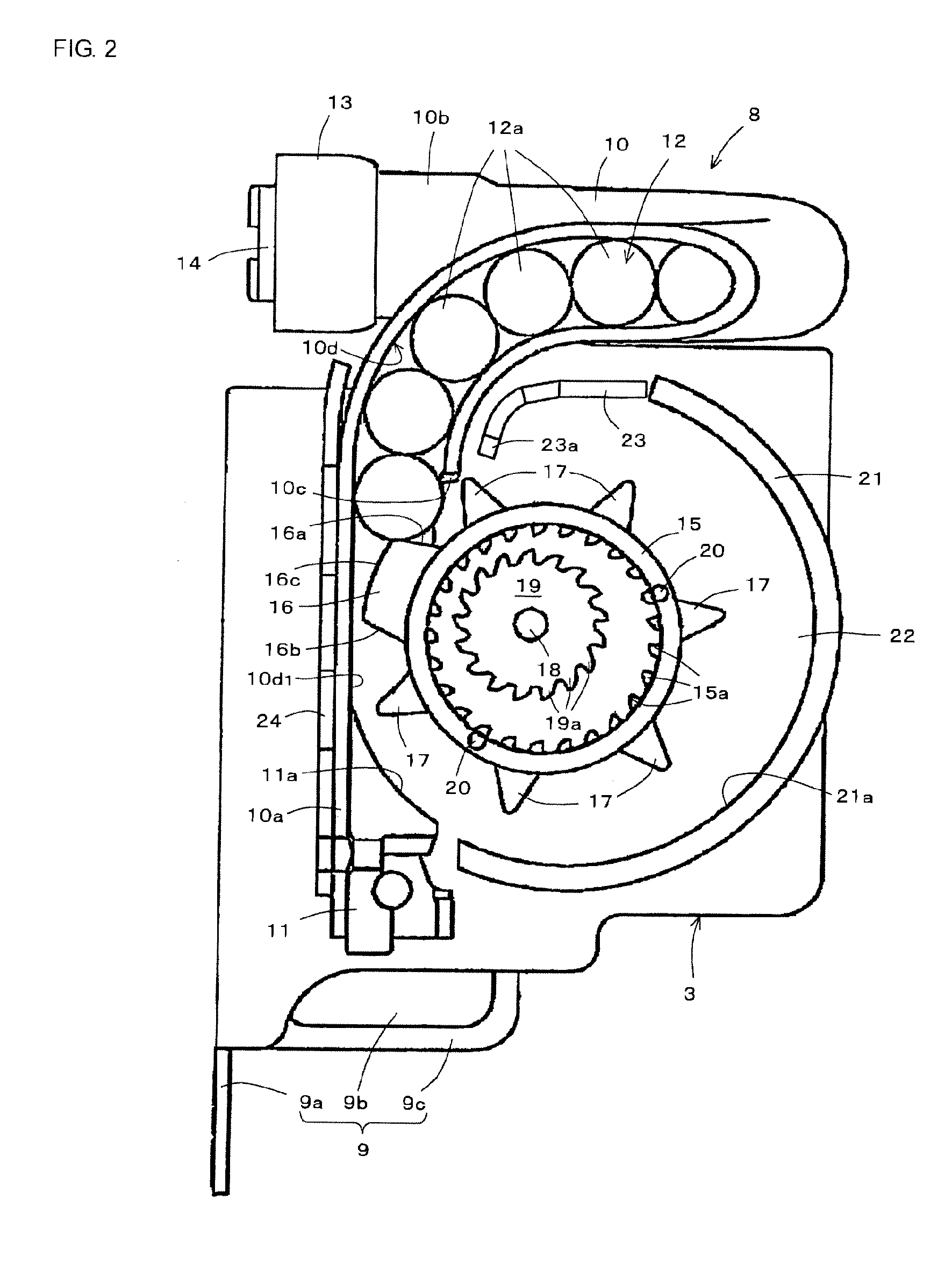
[0086]While a space to receive a part of one ball 12a is provided between a side edge 16b of a stopper 16 on a downstream side in the ring-gear rotating direction and a lever 17 in the above-described second embodiment illustrated in FIGS. 4(a) and 4(b), a pretensioner 8 of the third embodiment does not include, on a side edge 16b side of a stopper 16 on the downstream side in the ring-gear rotating direction, a space to receive a part of one ball 12a, as illustrated in FIGS. 5(a) and 5(b). Therefore, in the pretensioner B of the third embodiment, the number of levers 17 of a ring gear 15 is five, which is smaller by one than in the pretensioner 8 of the second embodiment illustrated in FIGS. 4(a) and 4(b).

[0087]According to the pretensioner 8 of the third embodiment, the space to receive a part of one ball 12a is not provided on the side edge 16b si...


PUM


Abstract

[Object] To allow force transmission members to smoothly move in a pipe, to facilitate setting of a stopper for stopping rotation of a ring gear, and to reduce the cost with a simple structure.
[Solution] A ring gear 15 of a pretensioner 8 includes a plurality of levers 17 and one arc-shaped stopper 16. During operation of the pretensioner 8, the levers 17 are sequentially pressed by balls 12a to rotate a pinion 19 and a spool in a seatbelt retracting direction. When the ring gear 15 rotates by a predetermined rotation amount, an outer peripheral edge 16c of the stopper 16 contacts and presses the opposing ball 12a. Since the ball 12a is thereby clamped between the stopper 16 and an inner peripheral surface 10d1 of a pipe 10, the ring gear 15 is stopped.

Description

TECHNICAL FIELD[0001]The present invention relates to a technical field of a pretensioner provided in a seatbelt retractor for retracting a seatbelt and using a plurality of force transmission members such as balls, a technical field of a seatbelt retractor, and a technical field of a vehicle seatbelt apparatus. BACKGROUND ART[0002]For seatbelt apparatuses to be mounted in vehicles such as cars, various seatbelt retractors including a pretensioner have been developed. In an initial stage of an emergency, such as a vehicle collision, when a deceleration higher than the normal deceleration is applied to the vehicle, this pretensioner rotates a spool of a seatbelt retractor in a seatbelt retracting direction by using reaction gas generated by a gas generator, thereby retracting a seatbelt around the spool. This quickly removes slack from the seatbelt and applies tension to the seatbelt so as to increase the occupant restraint force.[0003]As an example of a pretensioner of the related a...

Claims


Application Information

Patent Timeline
IPC IPC(8): B60R22/46
CPCB60R2022/4642B60R22/4628
Inventor TOMITA, HIROSHIHODATSU, YUICHIRO
Owner JOYSON SAFETY SYST JAPAN KK
Why Eureka
Try Eureka