Removable armrest for sectional seating

a sectional seating and armrest technology, applied in the field of armrests for pews and sectional seating, can solve the problems of insufficient armrests to meet the needs of the group, ineconomical practicality of retrofitting sectional seating with randomly placed permanent armrests, and insufficient armrest availability, etc., to achieve convenient folding up into a vertical position, quick installation, and secure removal

Inactive Publication Date: 2012-10-11
SELLERS VANDER J
View PDF11 Cites 0 Cited by
  • Summary
  • Abstract
  • Description
  • Claims
  • Application Information

AI Technical Summary

Benefits of technology

[0008]The device presented herein provides an armrest that can be quickly installed, secured and removed from sectional seating. This device can be readily secured to the top of the sectional seat back to lock the device into a stable position. In one embodiment of the device, it can be readily folded up into a vertical position when not in use to. In another embodiment of the device, it can be vertically adjusted to accommodate the preferences of the user while maintaining its structural and positional strength.

Problems solved by technology

In many instances, there are not enough armrests to meet the needs of the group using the seats.
The problem of inadequate availability of armrests is very prominent in the case with church pews.
In most cases, it is not economically practical to retrofit sectional seating with randomly placed permanent armrests.
Integral armrests are physically attached to the seat body using fasteners and are not readily removable from the seat body to which they are used.
Most of these prior art devices are either not capable being mountable on sectional seating such as pews, or do not lend themselves to rapidly being deployed, secured and removed.
Moreover, those that are rapidly deployable, lack adequate structural strength or adjustability to work across a broad range of weight forces applied to them.

Method used


Image

  • Removable armrest for sectional seating
  • Removable armrest for sectional seating
  • Removable armrest for sectional seating

Examples


Embodiment Construction

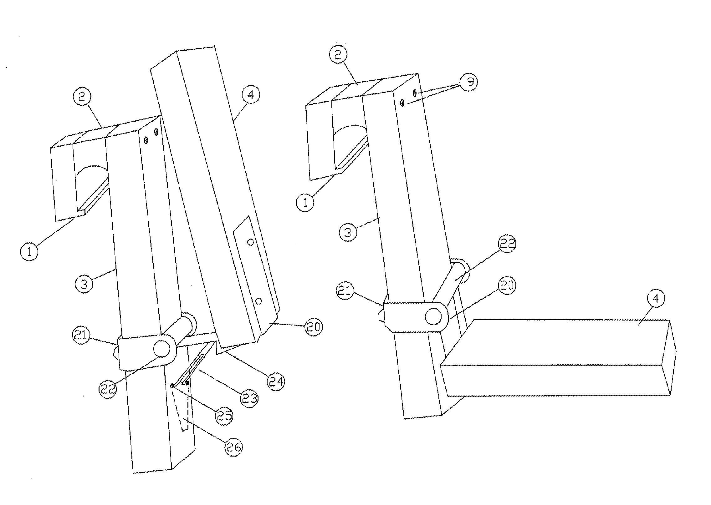
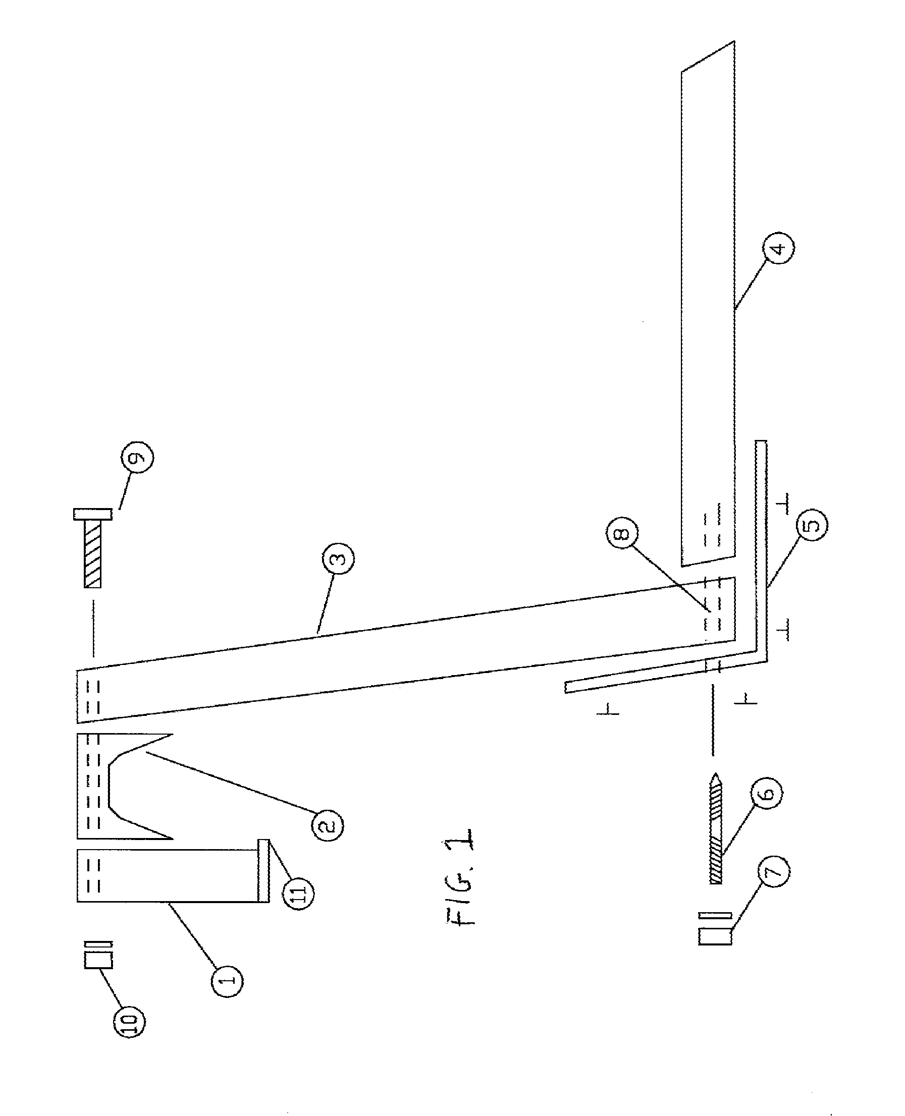
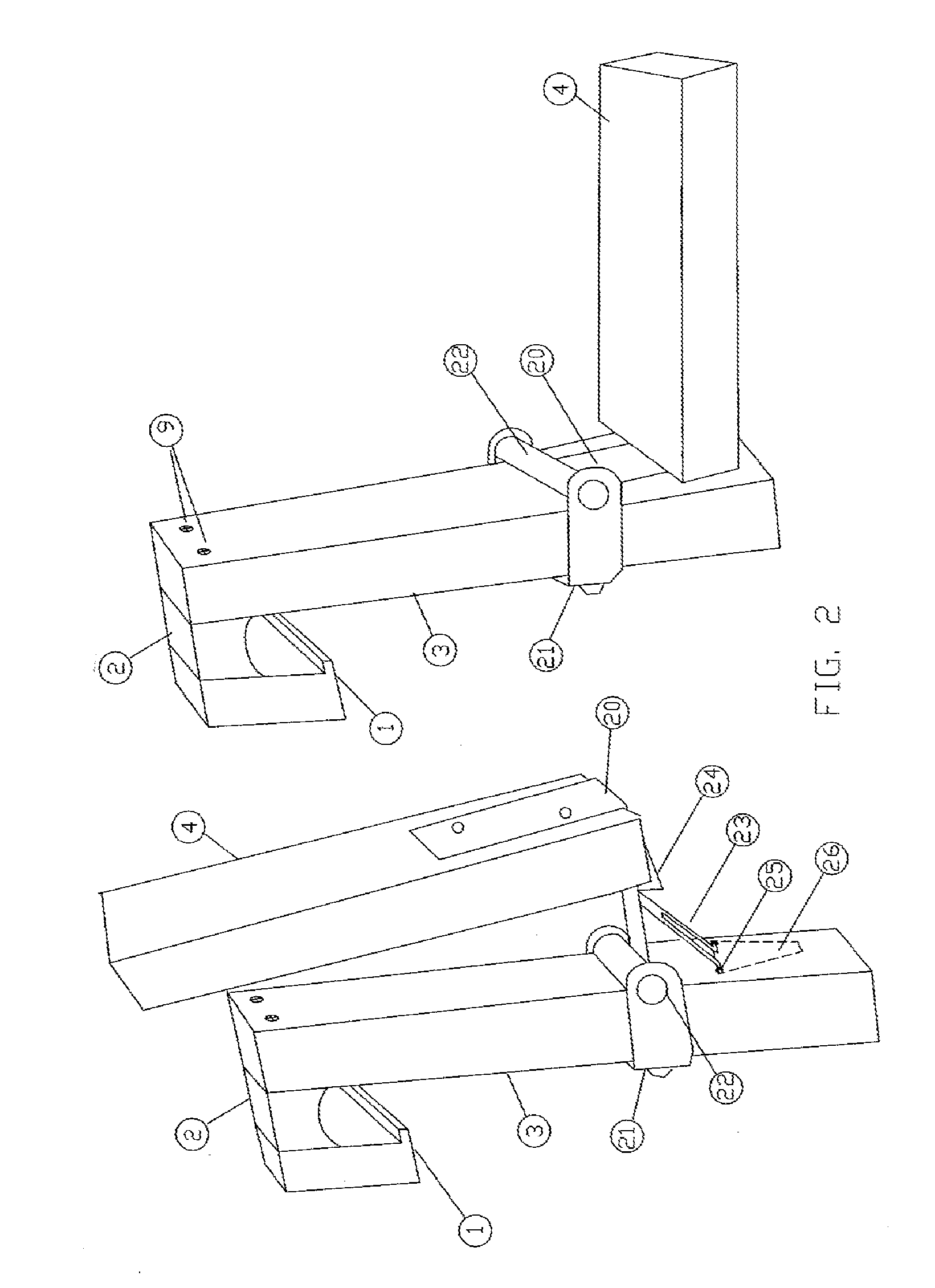
[0013]Referring in specific detail to the drawings, with common reference numbers identifying similar or identical elements, steps, and features, as shown in FIG. 1, the present disclosure describes a fixed-position armrest device for use with sectional seating, and in particular pews. In the illustrative embodiment shown in FIG. 1, the armrest device is comprised of a top clamp head 1, an adapting spacer 2, a vertical backboard 3, and the arm board 4. The device derives much of its structural strength from the clamping head assembly, which binds the device to the sectional seat back. With the top clamp fastener 9 and 10 loosened, the device is placed over the backboard of the sectional seat back at the desired location. For optimum binding strength, the downward facing of the adapting spacer 2 is shaped to match the top railing of the sectional seat back. Hence, it is a feature of this design that the adapting spacer can vary in width and face contour to accommodate a variety of fu...


PUM


Abstract

A detachable and adjustable armrest device for pews and sectional seating that can be quickly installed, moved, recessed and removed. The device includes an upper clamp that form-fits sectional seat backs and includes a plurality of adjustment fasteners that firmly secures the armrest to the top end of the sectional seat back. A vertical backboard extends down along the seat back at a common angle from the upper clamp assembly and provides a connecting point for the arm board. The arm board can be connected directly to the vertical backboard by an L-shaped bracket to provide a fixed height armrest. In an alternated embodiment, one end of the L-shaped bracket is connected to an axle that is affixed to the vertical backboard. When the arm board is lifted vertically, it pivots on the axle and can be held in a vertical recessed position of a lock pin. In another embodiment, one end of the L-shaped bracket is held against the vertical backboard by a plurality of guide clamps that allow for vertical movement of the arm board height relative to the vertical backboard. The height adjustment is made by turning a screw running vertically through the L-shaped bracket into a receiving nut attached to the underside of the vertical backboard.

Description

FIELD OF THE INVENTION[0001]The present invention relates generally to the field of accessories for chairs, pews and sectional seating, and in particular to armrests for pews and sectional seating.BACKGROUND OF THE INVENTION[0002]Sectional seating is typically comprised of two end sections and a long seat and back sections in between. The two end sections often provide the only armrests for the entire seating section. Frequently, people need the assistance of an armrest to provide a firm surface on which to push against to aid in going from a seated to a standing position, or vice versa. The people that most often need the assistance of an armrest for ingress and egress from sectional seating are the elderly, the disabled, and the sick. In many instances, there are not enough armrests to meet the needs of the group using the seats. Alternatively, persons needing the assistance of an armrest are forced to use seating in a less preferred location. The problem of inadequate availabilit...

Claims


Application Information

Patent Timeline
Patent Type & Authority Applications(United States)
IPC IPC(8): A47C7/54
CPCA47C7/546
Inventor SELLERS, VANDER J.
Owner SELLERS VANDER J
Why Eureka
Try Eureka