Systems and methods for calibrating dual polarization radar systems

a dual-polarization radar and system technology, applied in the field of dual-polarization radar systems, can solve the problems of many conventional calibration processes not being able to be performed while data is being collected, error causing inaccuracy in raw measurement data, and the normal operation of the radar system must be undetectedly suspended

Active Publication Date: 2012-10-11
BARON SERVICES
View PDF26 Cites 19 Cited by
  • Summary
  • Abstract
  • Description
  • Claims
  • Application Information

AI Technical Summary

Problems solved by technology

In transmitting pulses and measuring returns, a radar system may introduce error causing inaccuracies in the raw measurement data.
However, many conventional calibration processes cannot be performed while data is being gathered.
That is, the normal operation of the radar system must be undesirably suspended in order to perform the calibration process.
In addition, many conventional calibration processes are limited in the times that they can be performed such that the calibration process is performed less frequently than might be desired.
Thus, the actual measured reflectivity difference is indicative of the system error.
Unfortunately, for such calibration, the antenna of the radar system must be pointed to the raindrops directly above the antenna during the calibration thereby preventing the radar system from collecting data from geographic regions typically scanned by the system.
In addition, to provide optimum results, the measured raindrops should be within a certain size range, and there may a relatively long time between weather events that produce rain of the desired size directly over the radar system.
Indeed, in some geographic regions, opportunities to calibrate the radar system may be months apart.
For the calibration process to be successful, the Sun should be at a certain elevation relative to the radar system, and the times at which the calibration process can be run are thus limited.
In addition, when the calibration is being performed, the radar system is unable to collect data from geographic regions typically scanned by the system.
Thus a heretofore unaddressed need exists for a calibration process for dual polarization radar systems that can be performed more frequently and in the presence of various types of weather.

Method used


Image

  • Systems and methods for calibrating dual polarization radar systems
  • Systems and methods for calibrating dual polarization radar systems
  • Systems and methods for calibrating dual polarization radar systems

Examples


Embodiment Construction

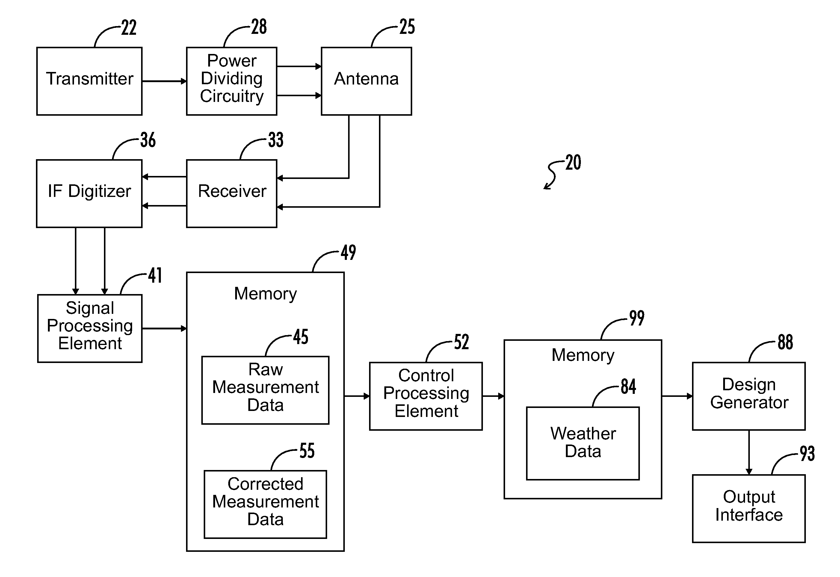
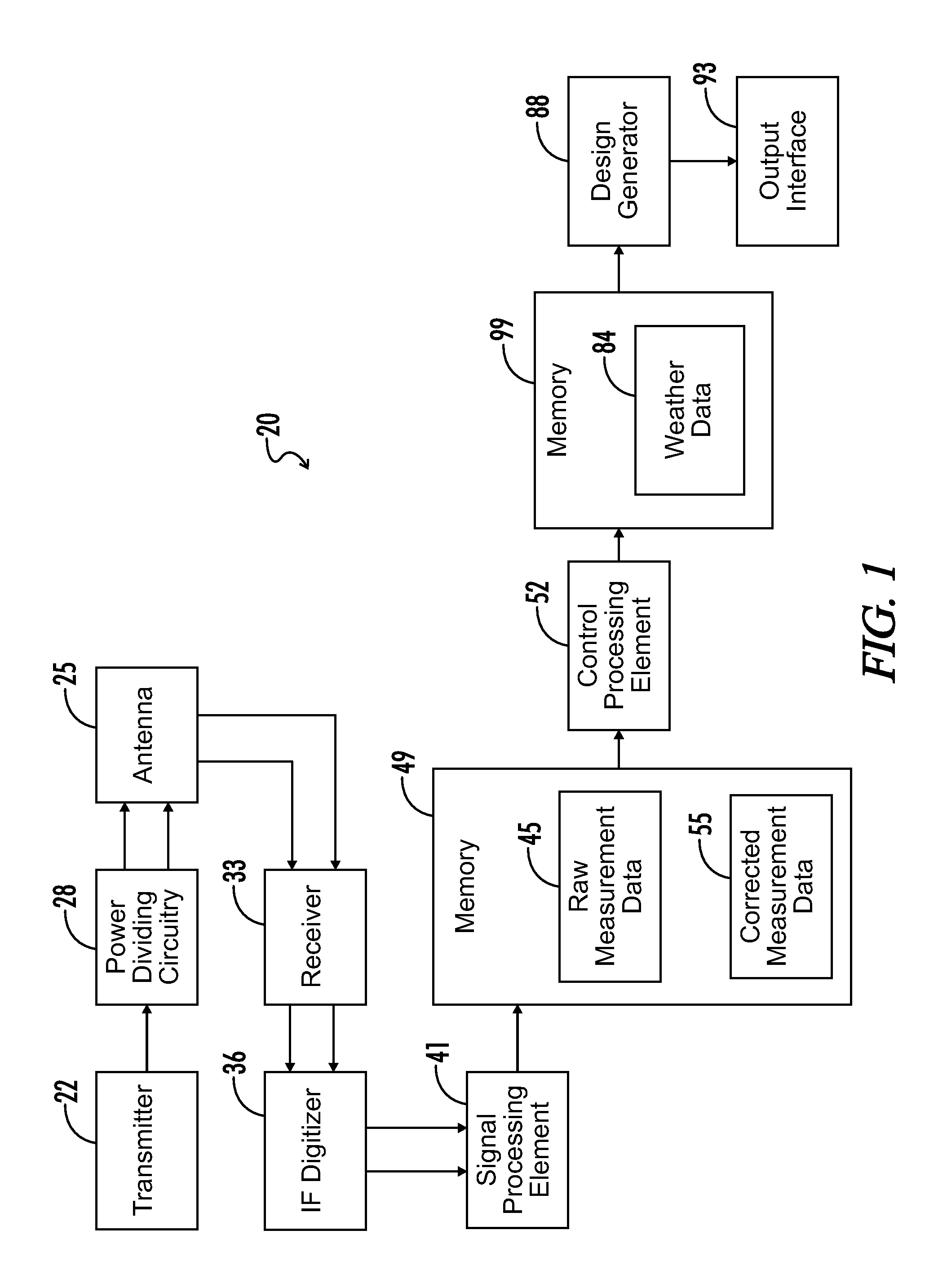
[0019]The present disclosure generally relates to systems and methods for calibrating dual polarization radar systems. In one exemplary embodiment, a dual polarization radar system is calibrated based on real-time data measurements, such as measured horizontal and vertical reflectivities, ZH and ZV. In this regard, the radar system analyzes the reflected power measurements to identify which measurements are associated with reflections from spherical objects. For such measurements, the differential reflectivity ZDR is ideally equal to zero, and the differential reflectivity indicated by the identified measurements is attributable to the system's differential reflectivity (ZDR—System). In this regard, for an actual differential reflectivity measurement, the measured differential reflectivity (ZDR) can be expressed according to the following equation:

ZDR=(ZH−ZV)+ZDR—System.

For a perfectly spherical target, (ZH−Zv) should be equal to zero such that the measured ZDR should be equal to ZD...


PUM


Abstract

A dual polarization radar system is calibrated based on real-time data measurements, such as measured horizontal and vertical reflectivities, ZH and ZV. In this regard, the radar system analyzes the reflected power measurements to identify which measurements are associated with reflections from a respective spherical object. Using such measurements, the system determines a system differential reflectivity value, and combines such value with reflected power measurements for calibration. Since the calibration is based on real-time data measurements, the calibration process may run simultaneously with the collection of weather data. Further, the calibration process is immune to the weather events within range of the radar system. Accordingly, it is possible for the calibration to be performed at any time and without interfering with the weather monitoring activities regardless of the types of weather events occurring within the vicinity of the radar system.

Description

CROSS REFERENCE TO RELATED APPLICATION[0001]This application claims priority to U.S. Provisional Patent Application No. 61 / 472,773, entitled “Systems and Methods for Calibrating Dual Polarization Radar Systems” and filed on Apr. 7, 2011, which is incorporated herein by reference.RELATED ART[0002]A dual polarization radar system transmits and measures the reflectivity of at least two waveforms, often a horizontally polarized waveform and a vertically polarized waveform. The difference between the horizontal reflectivity (ZH), which is a measure of the reflected power in the horizontally polarized return, and the vertical reflectivity (ZV), which is a measure of the reflected power in the vertically polarized return, is indicative of the shape of the radar target from which the waveforms are reflected, and this difference, referred to as “differential reflectivity” or “ZDR,” can be used to discern the type of meteorological scatterer, such as rain, sleet, hail, or snow or non-meteorol...

Claims


Application Information

Patent Timeline
Patent Type & Authority Applications(United States)
IPC IPC(8): G01S7/40
CPCG01S7/025G01S13/951G01S7/4021Y02A90/10
Inventor BALAJI, MRINAL SINGHELLIS, JR., JOHN R.CARTWRIGHT, R. DARRINWALKER, WILLIAM H.
Owner BARON SERVICES
Why Eureka
Try Eureka