Cranial Distractor

a distraction device and cranial bone technology, applied in the field of medical devices, can solve the problems of not optimal for bones possessing curved topographical configurations, and achieve the effect of reducing stress on the cranial distraction devi

Active Publication Date: 2012-10-11
KLS MARTIN LP
View PDF5 Cites 25 Cited by
  • Summary
  • Abstract
  • Description
  • Claims
  • Application Information

AI Technical Summary

Benefits of technology

[0005]The invention comprises in general a pair of cranial bone plates adapted for attachment to cranial bone segments, the cranial plates being mounted to a linear distraction mechanism such that the cranial plates can be separated gradually in very small increments. Each of the cranial plates is mounted to the distraction mechanism with a ball and socket connector assembly, such that each of the plates can move in multiple directions and orientations relative to the distraction mechanism to account for the topographical changes of the cranium during osteogenesis such that the configuration of the regenerated bone better matches the desired final configuration of the cranium while simultaneously reducing stress on the cranial distractor. One cranial plate is mounted to the distraction mechanism in stationary position while the other cranial plate is mounted in a manner that allows for movement along the longitudinal axis of the distraction mechanism in the direction away from the other cranial plate.

Problems solved by technology

Linear distraction is suitable for many bones, such as the mandible or the long bones of the legs or arms, but is not optimal for bones possessing curved topographical configurations, such as for example the cranium.
A problem with known distractors when used with cranial distraction is that the linear distractors fail to accommodate the curvature of the cranium, such that the distraction does not result in formation of new bone having or approximating the appropriate curvature, instead producing a more planar area of new bone.

Method used


Image

  • Cranial Distractor
  • Cranial Distractor
  • Cranial Distractor

Examples


Embodiment Construction

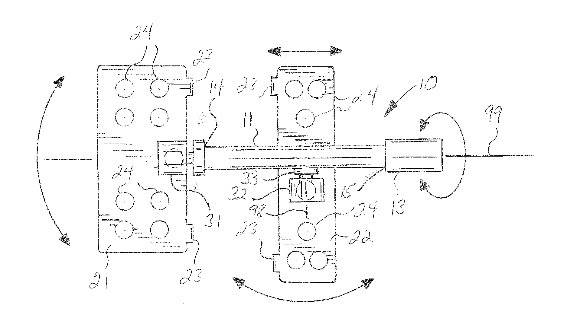
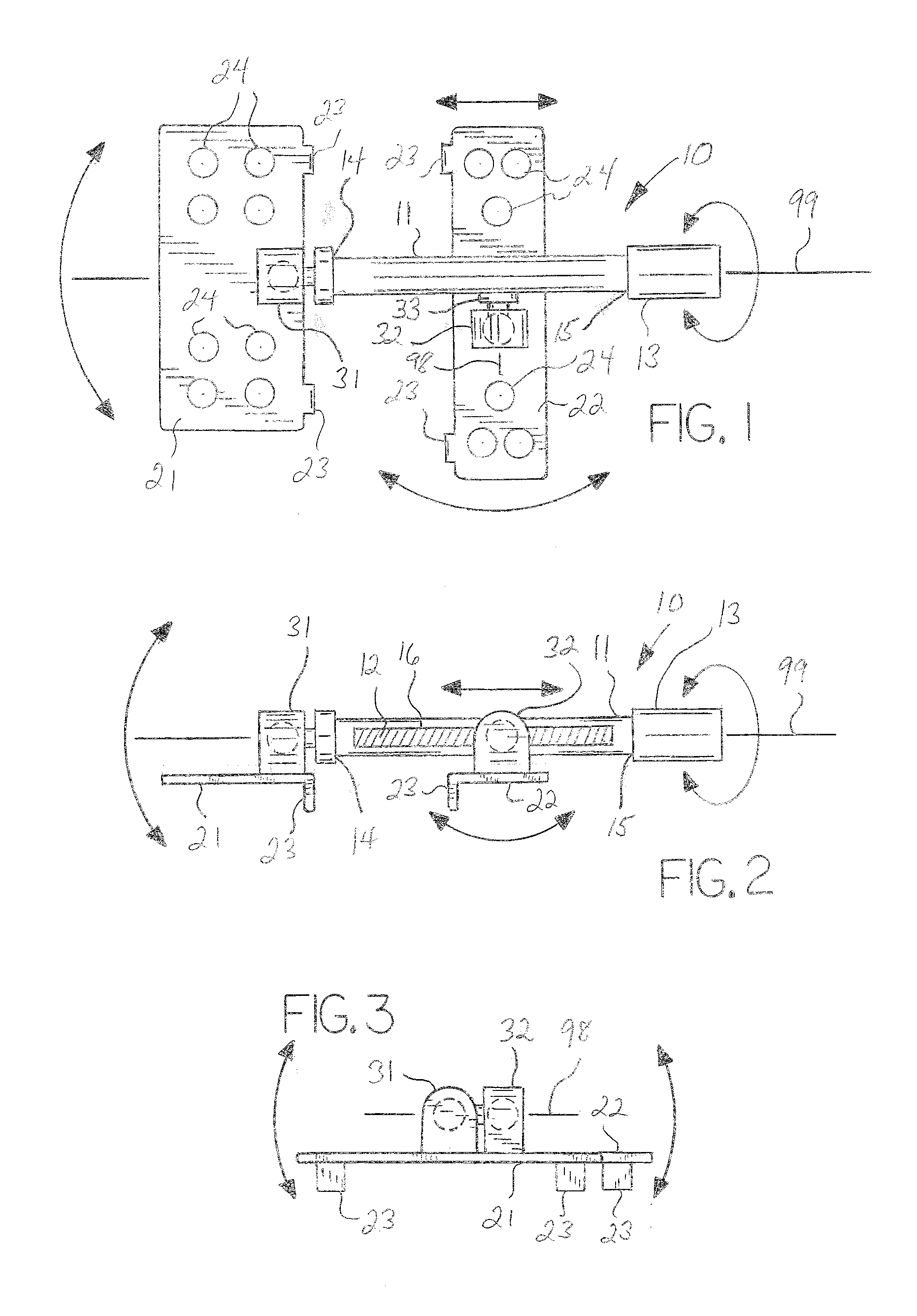
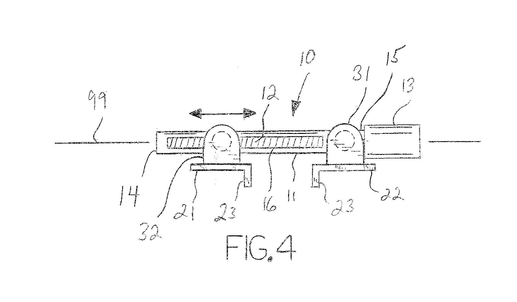
[0010]With reference to the drawings, which are meant to be illustrative and not limiting, the invention will now be described in detail with regard for the best mode and the preferred embodiment. In general, the invention is a cranial distractor comprising two cranial bone plates structured for affixation to opposing cranial segments using mechanical fasteners, adhesive bonding or other suitable means, the bone plates being connected to a linear distraction mechanism defining a longitudinal axis whereby operation of the distraction mechanism increases the distance between the bone plates. Each of the bone plates is connected to the distraction mechanism by a ball and socket connector assembly such that each bone plate may tilt up and down, rotate about the axis defined by the ball and socket connector assembly, and swivel side to side. With this structure the cranial plates of the distractor will properly orient relative to whatever convex, planar or concave surface topology is pre...


PUM


Abstract

A pair of bone plates adapted for attachment to cranial bone segments, the cranial plates being mounted to a distraction mechanism such that the cranial plates can be separated gradually in very small increments. Each of the cranial plates is mounted to the distraction mechanism with a ball and socket connector assembly, such that each of the plates can move in multiple directions and orientations relative to the distraction mechanism to better accommodate a convex, planar or concave surface topography presented during the distraction procedure.

Description

[0001]This application claims the benefit of U.S. Provisional Patent Application Ser. No. 61 / 516,557, filed Apr. 5, 2011, the disclosure of which is incorporated herein by reference.BACKGROUND OF THE INVENTION[0002]This invention relates broadly to the field of medical devices known generally as bone distractors, which are devices designed to allow the distance between two bone segments to be gradually increased while bone regenerates in the area between the bone segments. In particular, the invention relates to cranial bone distractors, which are devices applied to two bone segments of the cranium. The distractors comprise in general a pair of bone plates mounted to a distraction assembly.[0003]Bone regeneration or osteogenesis is a medical technique for repairing defective or damaged bones, such as for example when a bone fails to fully develop to its proper shape or size. An osteotomy or cut is made in the bone to produce two sides of exposed bone tissue and a distractor mechanis...

Claims


Application Information

Patent Timeline
Patent Type & Authority Applications(United States)
IPC IPC(8): A61B17/60
CPCA61B17/66A61B17/8061A61B17/8004
Inventor JOHNSTON, JR., THOMAS S.
Owner KLS MARTIN LP
Why Eureka
Try Eureka