
Measurement of invasion depth while drilling utilizing streaming potential

Inactive Publication Date: 2012-10-11
BAKER HUGHES INC
View PDF8 Cites 0 Cited by
  • Summary
  • Abstract
  • Description
  • Claims
  • Application Information

AI Technical Summary

Problems solved by technology

In borehole drilling, an over-balance between the pressure of the mud column and the formation can lead to mud filtrate invasion into pores of the rock defining the formation.

Method used


Image

  • Measurement of invasion depth while drilling utilizing streaming potential
  • Measurement of invasion depth while drilling utilizing streaming potential
  • Measurement of invasion depth while drilling utilizing streaming potential

Examples


Embodiment Construction

[0016]A detailed description of one or more embodiments of the disclosed apparatus and method presented herein is by way of exemplification and not limitation with reference to the Figures.

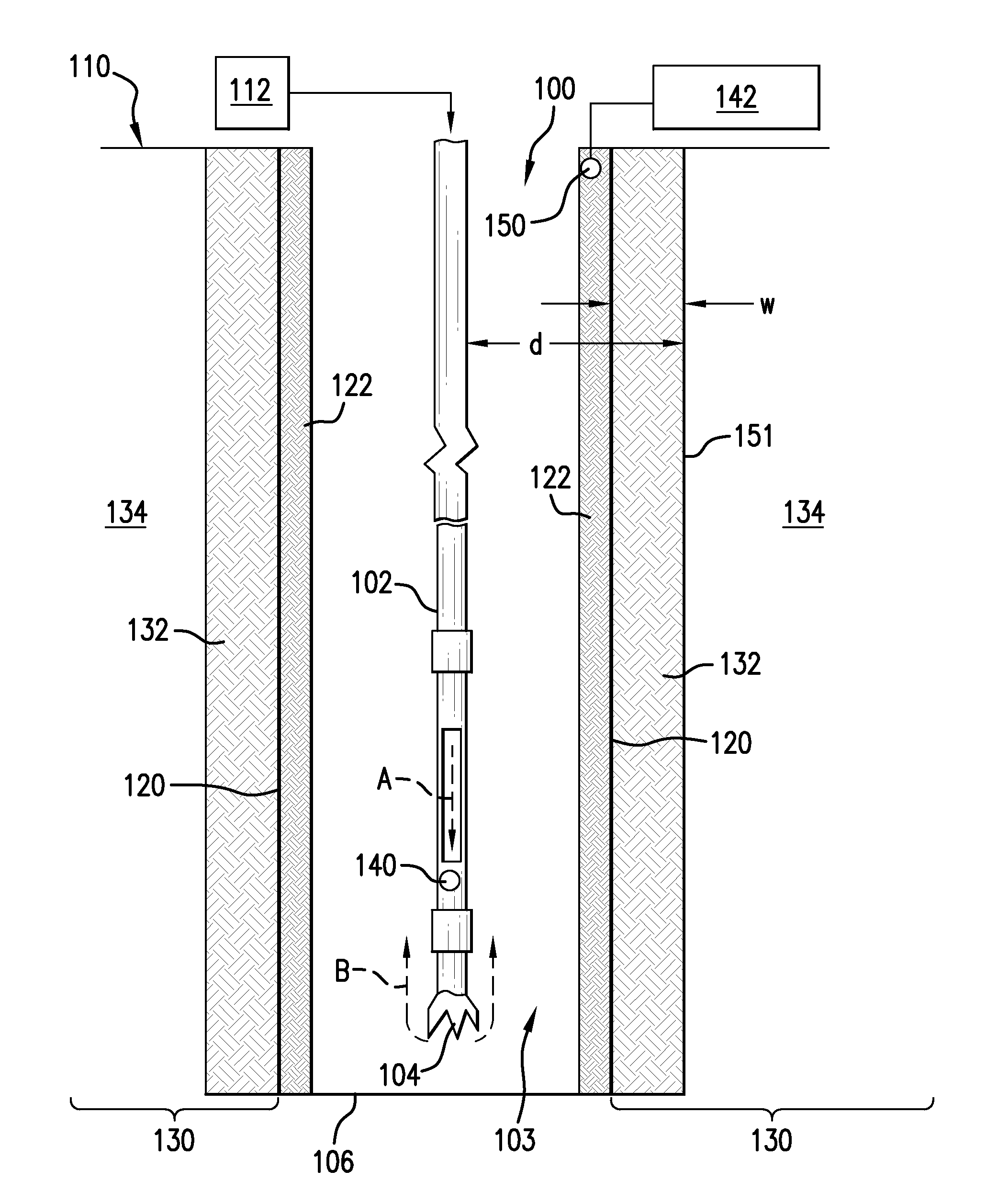
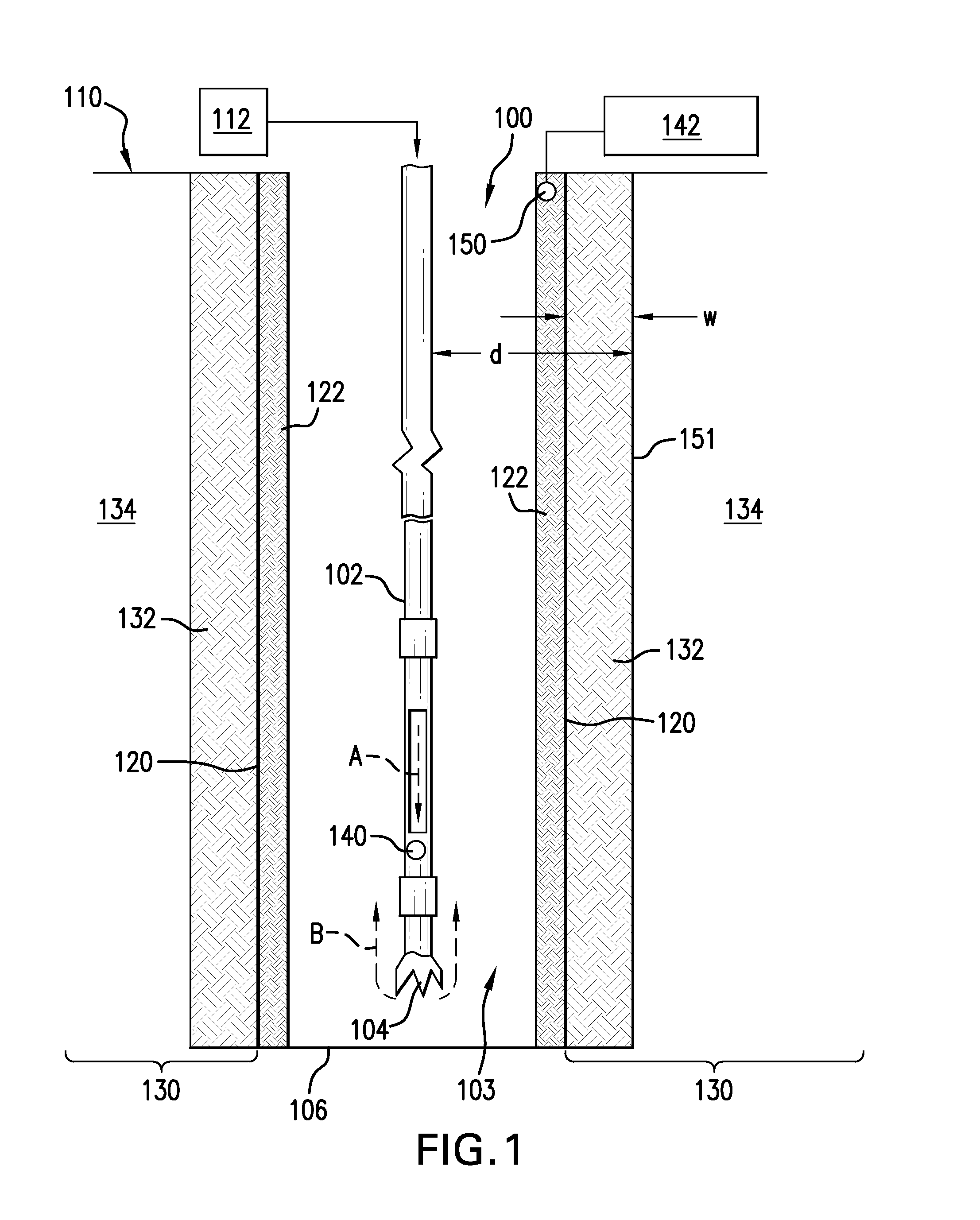
[0017]FIG. 1 shows a borehole 100 that is drilled by a drill string 102. The drill string 102 includes a drill bit 104 that is rotated by either rotation of the drill string 102 itself or by a motor (not shown) included in the drill string 102. The drill bit 104 pulverizes rock at the bottom 106 of the borehole 100 to elongate the borehole 100. It shall be understood that several implements located at the surface 110 are included to cause rotation of the drill bit 104. As such implements are well known, they are not discussed further herein. However, for a clearer understanding of embodiments disclosed herein one such implement in the form of mud pump 112 is illustrated. The mud pump 112 causes a drilling mud to be pumped into an internal portion of the drill string 102. At least some of the mud t...


PUM


Abstract

A system for determining an invasion depth of an invaded zone surrounding a borehole while the borehole is being drilled includes a sensor configured to be disposed in a mud cake formed on a wall of the borehole and configured to measure a property of the mud cake and a computing device configured to receive a measurement from the sensor and determine the invasion depth based on the measurement.

Description

CROSS-REFERENCE TO RELATED APPLICATIONS AND PRIORITY CLAIM[0001]This application claims the benefit of PCT Application No. PCT / RU2011 / 000683, entitled “MEASUREMENT OF INVASION DEPTH WHILE DRILLING UTILIZING STREAMING POTENTIAL”, filed Sep. 7, 2011, which is incorporated herein by reference in its entirety.BACKGROUND[0002]1. Field of the Invention[0003]The present invention generally relates to drilling and, in particular, to determining invasion depth while drilling.[0004]2. Description of the Related Art[0005]Boreholes are drilled deep into the earth for many applications such as carbon dioxide sequestration, geothermal production, and hydrocarbon exploration and production. In all of the applications, the boreholes are drilled such that they pass through or allow access to a material (e.g., a gas or fluid) contained in a formation located below the earth's surface. Many different types of tools and instruments may be disposed in the boreholes to perform various tasks and measureme...

Claims


Application Information

Patent Timeline
IPC IPC(8): G01V3/18G06F19/00
CPCG01V3/265G01V3/28G01V3/26G01V3/38
Inventor SHELUKHIN, VLADIMIR VALENTINOVICH
Owner BAKER HUGHES INC
Learn More