
Spring loaded security slot attachment for portable device security

a security slot and portable device technology, applied in the field of security slot attachments, can solve the problems of not showing a security slot engagement device, personal electronic device, tablet computer or notebook computer, and only as strong as the housing material, so as to facilitate pushing and enhance usability

Inactive Publication Date: 2012-10-18
THINK PROD
View PDF4 Cites 9 Cited by
  • Summary
  • Abstract
  • Description
  • Claims
  • Application Information

AI Technical Summary

Benefits of technology

"The present invention is a security slot attachment device that can be easily installed and removed without the use of tools. The attachment includes a locking bar and a plunger-type security lock. The locking bar is made of a cradle with a hingeably releasable pocket for inserting into the security slot of a device. The attachment is securely locked to the device and can be easily removed. The invention provides a simple and effective way to secure valuable equipment to prevent theft or unauthorized access."

Problems solved by technology

The prior art does not show a security slot engagement device that is inexpensive to manufacture, interfaces to a variety of locks or cables, has no separable parts, is easy to use, and requires no tools for installation or removal.
This leaves the personal electronic device, such as a tablet computer or notebook computer, vulnerable to theft.
Also like the '056 patent, however, the security provided by the '350 patent is only as strong as the housing material and therefore slot integrity.

Method used


Image

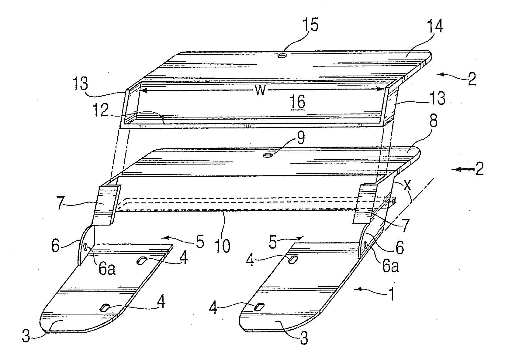
  • Spring loaded security slot attachment for portable device security
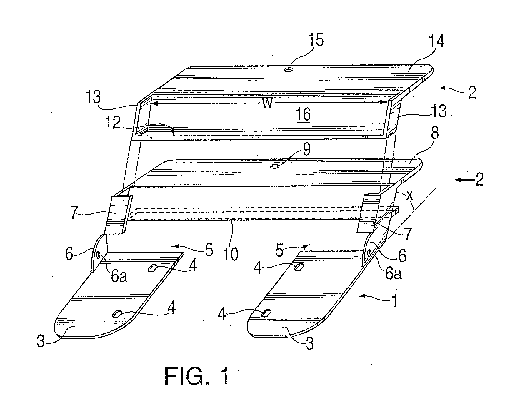
  • Spring loaded security slot attachment for portable device security
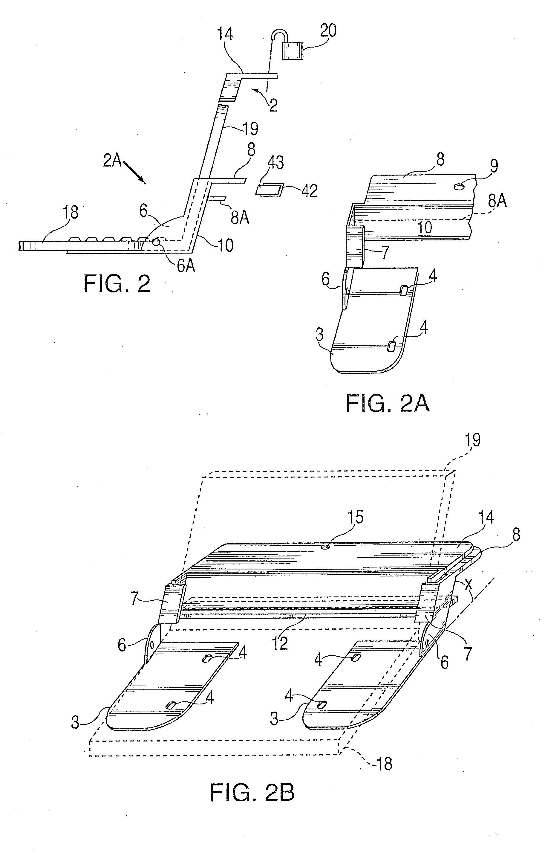
  • Spring loaded security slot attachment for portable device security

Examples


embodiment 640

[0228]Another adjustable embodiment 640 shown in FIG. 65 uses a two-part telescoping metal chassis bar consisting of hollow proximal portion 646 and solid distal portion 642 which fits inside. An array of holes 644 provides adjustability by virtue of friction fit pin 648 with a large flat head. Again, this pin is locked once tablet 601 is installed. This embodiment is more compact for smaller tablets or like items since there is no distal metal bar extending beyond the distal engagement pocket as in embodiment of FIG. 64.

[0229]A further embodiment for a security slot attachment assembly is shown in FIGS. 66-79.

[0230]FIG. 66 shows a detail view in partial cutaway of an equipment (e.g., a laptop) housing 700 with security slot 710. This slot is preferably approximately 3 mm by 7 mm, although dimensions may vary with varying equipment.

[0231]FIG. 67 shows the security slot attachment 720 of this invention installed to equipment housing 700.

[0232]FIG. 68 shows a lock 721 engaged with a s...

first embodiment

[0239]FIGS. 75 through 79 show details of an alternative embodiment of security slot attachment 795 of this invention. In this embodiment, two parts of the security slot attachment 720 (FIGS. 67-74) are modified. That is, pivot block 780 of security slot attachment 795 in FIG. 75 replaces pivot block 750 of security slot attachment 720, but its function and attachment remain the same. The three rounded corners of pivot block 780 permit a closer fit and in some cases better accommodate operational clearances. The other modified part (with respect to security slot attachment 720) is guide 790 (see FIG. 76). Guide 790 replaces guide 740 of the first embodiment disclosed in FIGS. 67-74 herein. Exterior portion 791 of guide 790, which includes extended wings 791 is now wider than front portion 741 of guide 740 of security slot attachment 720:

[0240]An assembly of an embodiment of security slot attachment 795 is shown in FIGS. 77, 78 and 79. It is noted that there is only one locking posit...


PUM


Abstract

A lock includes an assembly of a slot engaging member insertable in a slot of a piece of equipment being locked, such as a portable or desktop computer, a laptop, notebook or other handheld electronic device, a monitor, a television / video screen, a video game, an electronic instrument such as an oscillator or a medical centrifuge or other analytical device, or the like. A rotatable locking member engages an anchor sub-assembly having a rotatable element, wherein the rotatable element communicates with a spring force urging against the rotatable locking member. The rotatable locking member is alternately movable in and out of the slot in which it is inserted, and the locking element is rotatable by finger force overcoming said spring force against the locking member, wherein the lock is locked without use of a tool.

Description

RELATED APPLICATIONS[0001]This application is a continuation-in-part (“CIP”) of U.S. application Ser. No. 13 / 365,222 filed Feb. 2, 2012, which application is a continuation-in-part (“CIP”) of U.S. application Ser. No. 13 / 031,174, filed Feb. 18, 2011, which application is a continuation-in-part (“CIP”) of U.S. application Ser. No. 12 / 657,670, filed Jan. 25, 2010, which '670 application is a continuation-in-part (CIP) application of U.S. application Ser. No. 12 / 154,561, filed May 23, 2008 ('561 application), which '561 application is a CIP application of U.S. application Ser. No. 11 / 454,433, filed Jun. 16, 2006 ('433 application), which '433 application is a CIP application of U.S. application Ser. No. 11 / 359,871, filed Feb. 22, 2006 ('871 application), which '871 application is a CIP application that claims priority from a) U.S. Provisional Appln. No. 60 / 655,270, filed Feb. 22, 2005, b) Provisional Appln. No. 60 / 678,911, filed May 6, 2005 and c) U.S. application Ser. No. 11 / 038,591, ...

Claims


Application Information

Patent Timeline
Patent Type & Authority Applications(United States)
IPC IPC(8): E05B73/00
CPCE05B73/0082E05B73/0005Y10T70/402Y10T70/485Y10T70/5009
Inventor ALLEN, PETERMARSZALEK, ANDRZEJ
Owner THINK PROD
Learn More