Method and apparatus for determining proper curing of pipe liners using distributed temperature sensing

a temperature sensing and temperature sensing technology, applied in the direction of instruments, heat measurement, mechanical control devices, etc., can solve the problems of affecting the operation of the entire lining, affecting the operation of the lining, and requiring replacement or repair. , to achieve the effect of reducing the risk of leaking or failing structurally, reducing the risk of leaking, and reducing the efficiency of lining operation

Inactive Publication Date: 2012-10-18
ENVIROSIGHT
View PDF8 Cites 9 Cited by
  • Summary
  • Abstract
  • Description
  • Claims
  • Application Information

AI Technical Summary

Problems solved by technology

As pipes age, they begin to leak or fail structurally and require replacement or repair.
Replacing pipes, especially underground, can be extremely difficult and expensive.
However, Applicants have found that significant temperature variations exist along the liner so that a single temperature gauge does not provide sufficient information to confirm that the temperature is within the prescribed range along the entire pipe so to assure proper curing over the entire length of the lining, especially as the lengths of the segment become longer.
If the liner is not completely cured over its full length, the entire lining operation may be compromised.
Many factors can contribute to temperature variations within the lining, such as poor heating fluid circulation.
If the entire length of the liner has not been properly cured, the entire installation may be at risk of failing.
Such solutions are costly, time consuming and / or labor intensive.
Yet further, they are relatively bulky components that commonly remain in the pipe after installation and impede the flow of fluid within the pipe.

Method used


Image

  • Method and apparatus for determining proper curing of pipe liners using distributed temperature sensing
  • Method and apparatus for determining proper curing of pipe liners using distributed temperature sensing
  • Method and apparatus for determining proper curing of pipe liners using distributed temperature sensing

Examples


Embodiment Construction

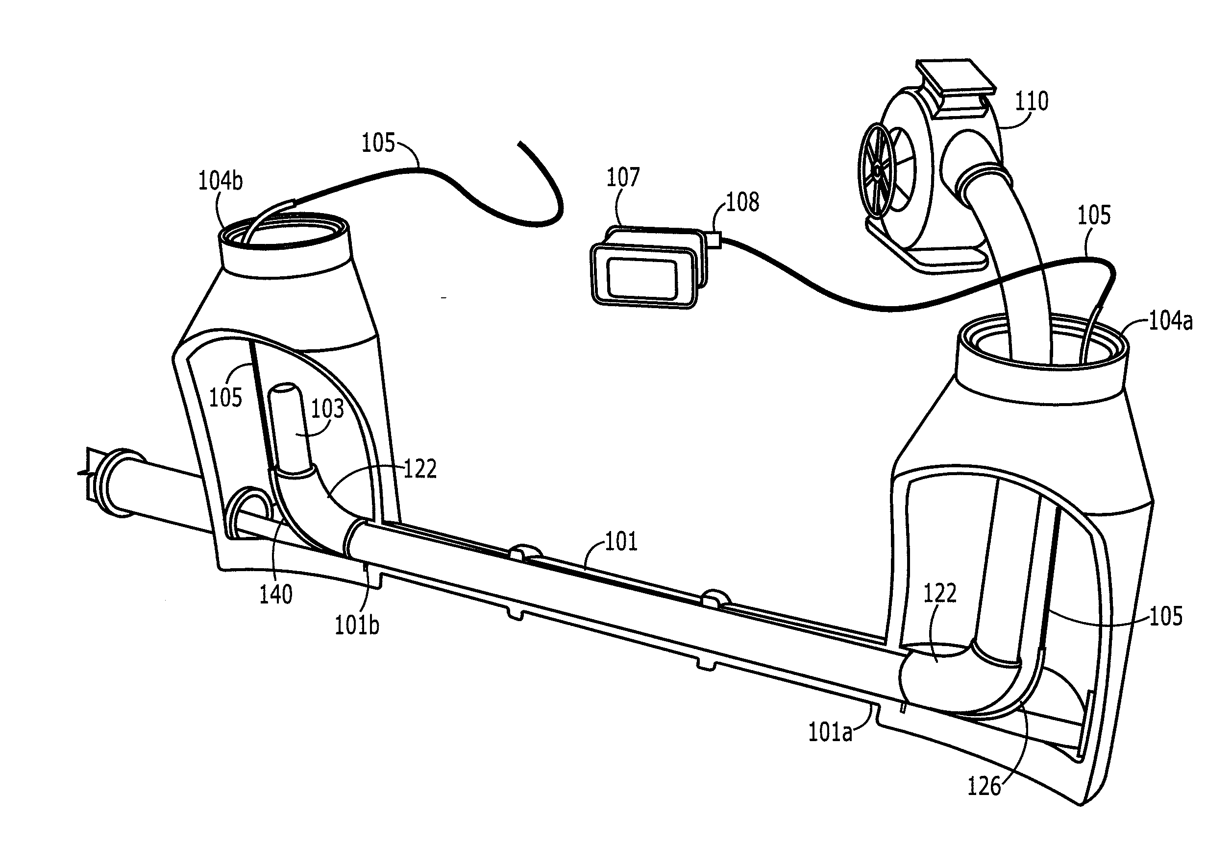
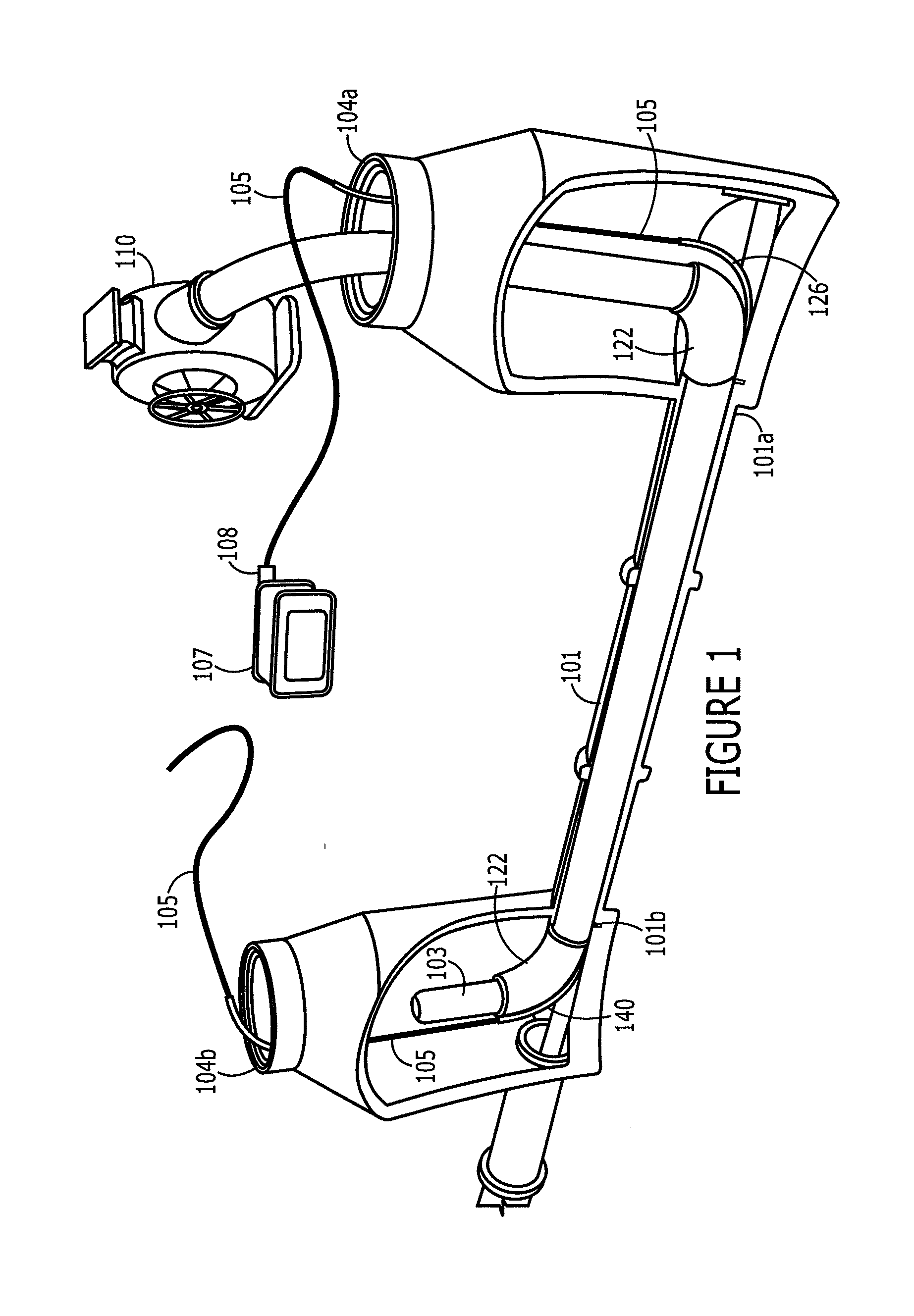
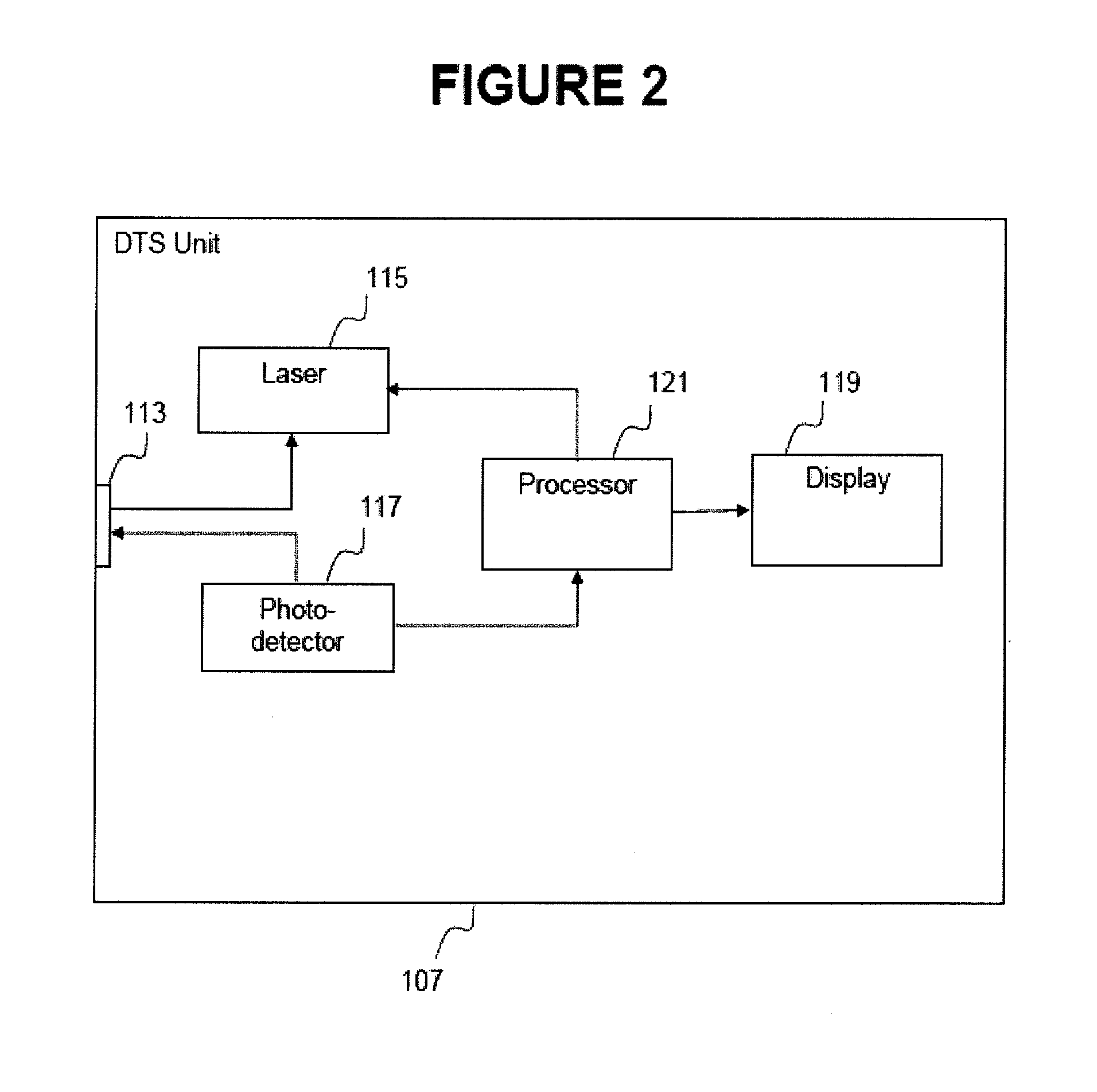
[0020]FIG. 1 is a schematic diagram of a pipe segment in the process of being lined according to one embodiment of the present invention and showing the various components involved in the practice of one embodiment of the present invention. FIG. 1 shows the process near an end stage so as to illustrate all of the components involved. Particularly, a segment of pipe 101, such as sewer pipe that is in need of repair, is disposed underground and is accessible only at discrete points adjacent first and second manholes 104a, 104b in the street, e.g., commonly spaced apart approximately 360-400 feet in the United States. Accordingly, a 360-400 foot long sock of cured-in-place pipe liner 103 is provided for lining the pipe 101. Before the liner 103 is placed in the pipe 101, an optical fiber cable 105 is placed in the pipe 101. In one embodiment, the optical fiber cable is longer than the actual pipe segment such that the distal end of the cable extends approximately ten meters or so from ...


PUM

PropertyMeasurementUnit
pressureaaaaaaaaaa
pressureaaaaaaaaaa
temperatureaaaaaaaaaa

Abstract

The present invention relates to methods and apparatus utilizing distributed temperature sensing (DTS) to monitor the temperature of a cured-in-place pipe liner to determine if proper curing temperatures and times are achieved. More particularly, an optical fiber is placed between the pipe and the liner running the entire length of the liner. The optical fiber is coupled to a DTS unit. During curing of the liner, the DTS unit sends light pulses down the fiber from one end and detects the characteristics and time delay of light backscattered to the unit. The characteristics are indicative of the temperature of the optical fiber, while the delay is indicative of the round trip time of the light within the fiber, and thus the distance from the DTS unit from which any particular backscatter signal originated.

Description

CROSS REFERENCE TO RELATED APPLICATIONS[0001]This continuation application is based on, and claims priority to, U.S. Provisional Application No. 61 / 473,459, filed Apr. 8, 2011, and U.S. Non-Provisional application Ser. No. 13 / 085,963, filed Apr. 13, 2011, and U.S. Non-Provisional application Ser. No. 13 / 417,815, filed Mar. 12, 2012, the entire contents of which are fully incorporated herein by reference.FIELD OF THE INVENTION[0002]The invention relates generally to the curing of cured-in-place pipe liners. More specifically, the invention relates to a method and apparatus for assuring that a cure-in-place liner installed in a pipe is fully cured.BACKGROUND OF THE INVENTION[0003]It is often necessary to repair pipes, tubes and the like, such as sewer pipes, that are disposed in locations that are difficult or impossible to access. Some such situations are encountered in connection with underground sewer, storm water, potable water, gas, and other utility pipes. As pipes age, they beg...

Claims


Application Information

Patent Timeline
Patent Type & Authority Applications(United States)
IPC IPC(8): B29C65/02B32B41/00
CPCB32B37/02B32B37/06B32B41/00B32B37/14B32B37/10G01K11/32G01K13/00G01K11/324
Inventor LINDNER, RICHARDGEARHART, STEPHEN VINCENT
Owner ENVIROSIGHT
Why Eureka
Try Eureka