
Electromagnetic and its combined surveying apparatus and method

a combined surveying and electromagnetic technology, applied in the field of electromagnetic and its combined surveying apparatus and method, can solve the problems of not being able to create a distributed receiver station comprising hundred or thousand receivers, the mentioned patents disclose a small size of electromagnetic transmitters, and the above mentioned patents disclose the use of the same distributed receivers. , to achieve the effect of convenient towed by the truck and setup, convenient movement and implementation, and saving setup tim

Active Publication Date: 2012-10-18
WHAN WEN J
View PDF4 Cites 23 Cited by
  • Summary
  • Abstract
  • Description
  • Claims
  • Application Information

AI Technical Summary

Benefits of technology

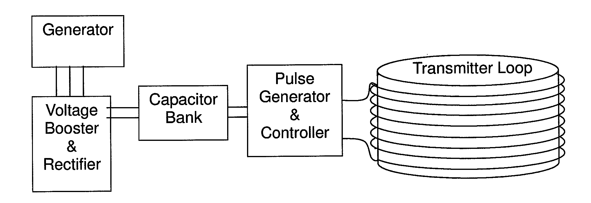
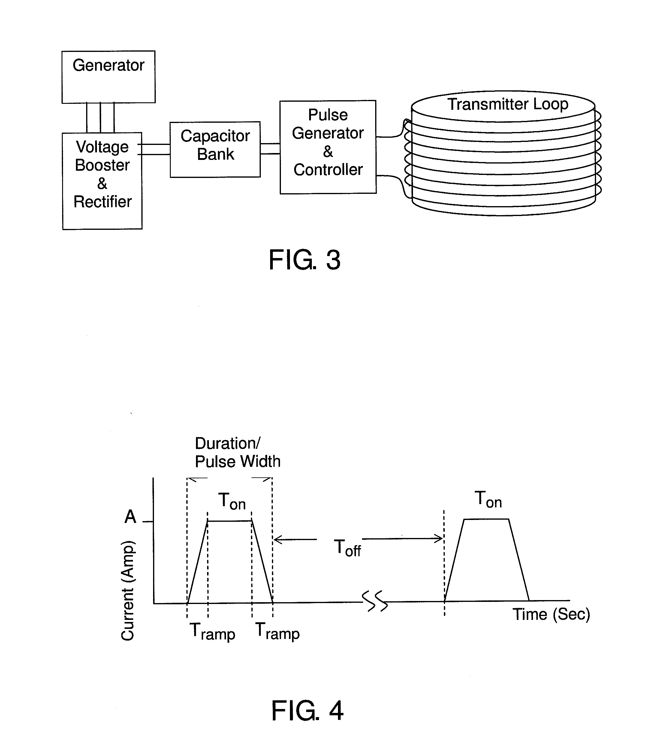
[0009]An object of the present invention is to provide an electromagnetic and its combined surveying apparatus and method, where the adopted transmitters are small-sized so that it would be easy to be moved and implemented at the field site; multiple transmitters could be linked to give multiple power or work alternatively in order to save setup time; and each transmitter includes a wire loop or a loop connected by metal rods, which are easy to be towed by the trucks and setup at field.

Problems solved by technology

Due to the size and weight of the conventional receivers, it is almost impossible to create a distributed receiver station comprising hundred or thousand receivers.
However, none of the above mentioned patents disclose a small size of electromagnetic transmitter with variable spectrum for variable deep sounding penetration and easy movement.
However, none of the above mentioned patents disclose usage of the same distributed receivers with magnetic field sensors and geophones or MEMS (Micro Electro-Mechanical System) accelerometers for electromagnetic exploration and seismic exploration.

Method used


Image

  • Electromagnetic and its combined surveying apparatus and method
  • Electromagnetic and its combined surveying apparatus and method
  • Electromagnetic and its combined surveying apparatus and method

Examples


Embodiment Construction

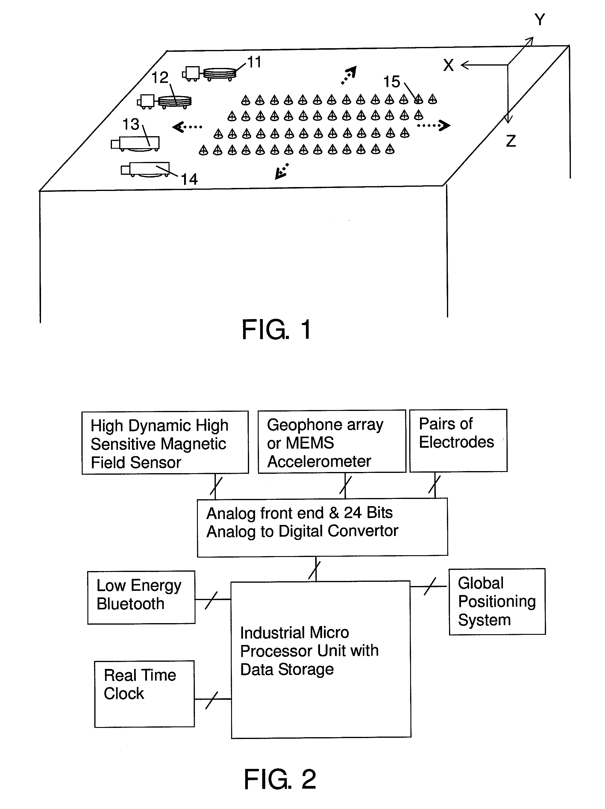
[0027]The present invention discloses an electromagnetic and its combined surveying apparatus and method by means of electromagnetic exploration or combined magneto-telluric and seismic exploration; said apparatus comprising a plurality of receivers and a plurality of mobile actuate electromagnetic and / or seismic sources. The plurality of receivers are distributed over the area to be explored, each of which is connected with at least one of a one-component or three-component portable magnetic field sensor, geophones or MEMS (Micro Electro-Mechanical System) accelerometers, and at least a pair of electrodes, for receiving and recording the one or three-dimensional magnetic field data from the portable magnetic field sensor, and / or seismic data from the geophones or MEMS accelerometers, and / or electric field data from the pair of electrodes. The plurality of mobile actuate electromagnetic and / or seismic sources are moved in the vicinity of the receivers or rolled together with the rec...


PUM


Abstract

An electromagnetic and its combined surveying apparatus and method, utilizing small-sized one or three-dimensional magnetic field sensors with high dynamic range and high sensitivity, which can be used together with highly populated receivers for the electromagnetic exploration. The electrical field could be derived from the vertical component of the magnetic field of the highly populated receivers and the magneto-telluric data could be derived by measuring the three components of the magnetic data. Moreover, by means of connecting the same populated receivers with geophones or MEMS accelerometers, and moving the seismic sources together with the mobile electromagnetic source, seismic survey could be carried out. It is therefore able to undertake the interpretation of the seismic, electromagnetic and magneto-telluric data and perform a combined field exploration

Description

TECHNICAL FIELD[0001]The present invention relates to an electromagnetic and its combined surveying apparatus and method, utilizing small-sized one or three-dimensional magnetic field sensors with high dynamic range and high sensitivity, which can be used together with highly populated receivers for the electromagnetic exploration. The electrical field could be derived from the vertical component of the magnetic field of the highly populated receivers and the magneto-telluric data could be derived by measuring the three components of the magnetic data. Moreover, by means of connecting the same populated receivers together with geophones and MEMS (Micro Electro-Mechanical System) accelerometers, and moving the seismic sources together with the mobile electromagnetic source, seismic survey could be carried out. It is therefore able to undertake the interpretation of the seismic, electromagnetic and magneto-telluric data and perform a combined field exploration.BACKGROUND[0002]The conv...

Claims


Application Information

Patent Timeline
IPC IPC(8): G01V3/12G01V1/00G01V3/08
CPCG01V2210/6163G01V11/00
Inventor WHAN, WEN J.XU, DAKUN
Owner WHAN WEN J
Learn More