Wiper member for a container

a container and wiper technology, applied in the field of wiper assembly, can solve the problems of smearing on the face, hands, or hair of users, loss of integrity of the wiper, etc., and achieve the effect of eliminating the condition of reverse wiping and efficient wiping of residue/excess produ

a container and wiper technology, applied in the field of wiper assembly, can solve the problems of smearing on the face, hands, or hair of users, loss of integrity of the wiper, etc., and achieve the effect of eliminating the condition of reverse wiping and efficient wiping of residue/excess produ

US20120263515A1Active Publication Date: 2012-10-18ZEN DESIGN SOLUTIONS

Image

  • Wiper member for a container
  • Wiper member for a container
  • Wiper member for a container

Examples


Embodiment Construction

[0038]The wiper member of a container according to one embodiment of the present invention is shown in FIGS. 1 through to 5.

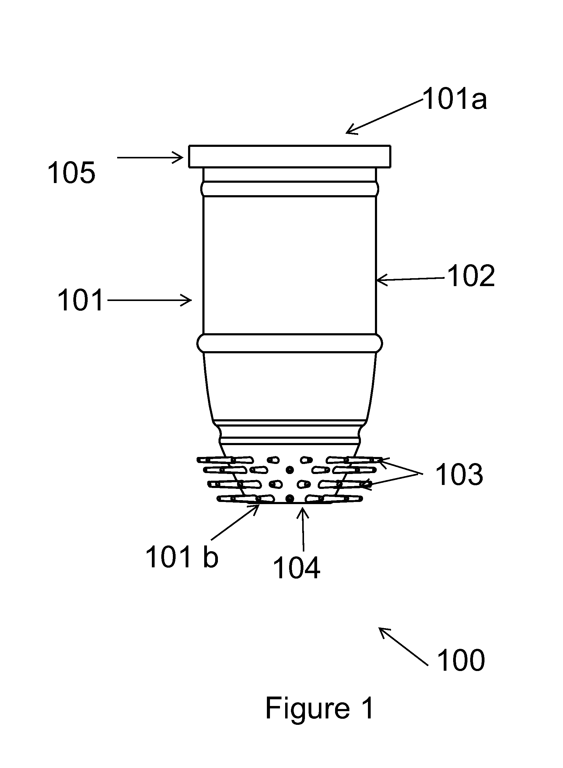
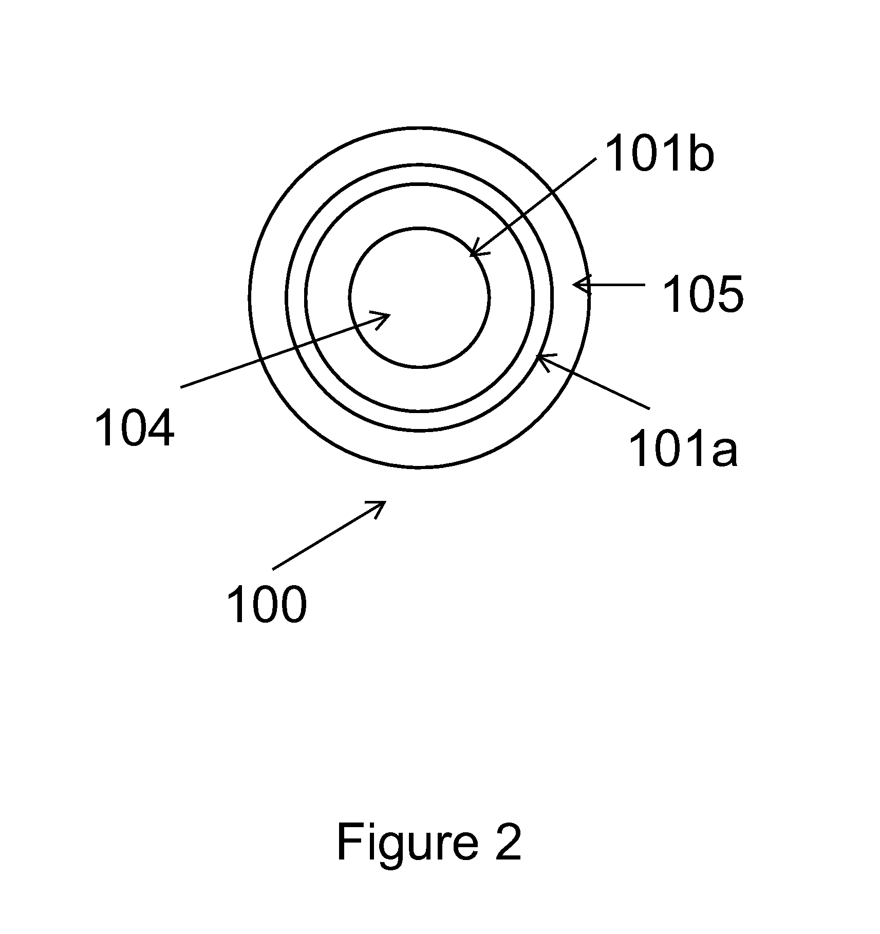
[0039]FIG. 1 is one embodiment of the present invention showing the wiper member 100. The wiper member 100 of the present invention comprises a housing 101, said housing having a proximal end 101a and a distal end 101b, both the ends defining an opening 104. The proximal end 101a further defines a neck 105. The housing 101 of the wiper member 100 comprises at least one sidewall 102 and there are present a plurality of protrusions 103 on the outer diameter of the sidewall 102. The protrusions 103 extend outwards from the outer diameter of the sidewall 102 of the wiper member 100. The plurality of protrusions 103 as shown in FIG. 1 occupy half the area near the distal end 101b of the wiper member, however, the protrusions 103 may occupy any suitable proportion of the outer diameter of the sidewall 102 of the wiper member 100. Further, there may be present a lip b...


PUM


Abstract

The present invention generally is a container for packaging and dispensing cosmetic or care products. More particularly, the invention relates to a wiper member used in such a container. There is provided a wiper member that is novel and inventive by way of its construction such that the wiper member comprises a housing wherein said housing is having at least one sidewall, wherein the wiper sidewall takes up a wiping configuration and a non-wiping configuration when a component is caused to travel through the housing.

Description

BACKGROUND[0001]1. Field of the Invention[0002]Embodiments of the present invention described herein generally relate to a wiper assembly and in particular, relate to a wiper assembly that performs wiping action by determining the presence of the tool to be wiped. The wiper assembly of the present invention presents a wiping and a non-wiping configuration by detecting the directional movement of the applicator.[0003]Wiper member of the present invention can be employed in application of various products, such as for viscous cosmetics, mascara, eye liner, lip gloss, coloring strands of hair and like products.[0004]2. Description of the Related Art[0005]Typical packaging and applicator devices include a tubular container having a cap and in the cap is integrated a stem containing the applicator at its distal end thereby allowing the cap to serve as a handle to hold the applicator as well. Such devices generally also include a wiper element situated at the neck of the container that he...

Claims


Application Information

Patent Timeline
18 Oct 2012
Publication
US20120263515A1
IPC
A45D40/26
CPC
A45D40/267
Inventors
PIRES, LEO CLIFFORD; HWANG, ROGER