Mounting tool for a vehicle wheel

Inactive Publication Date: 2012-10-25
SUGITO SRI URIPTO
View PDF2 Cites 2 Cited by
  • Summary
  • Abstract
  • Description
  • Claims
  • Application Information

AI Technical Summary

Benefits of technology

[0004]After such dredged sticks attached with bolts of wheel drum, pull its handle up slowly, said wheel on directive stick slides down easily heading to wheel drum.
[0005]Using present invention, wheel assembly of vehicle will be easier and instantly.
[0006]Purpose of present invention is to ease wheel assembly on wheel drum, to work in shorter time and easy.SUMMARY OF FIGURE

Problems solved by technology

Conventional wheel assembly has some obstacles, fitting bolts into car's rim in particular, which are located in drum of wheel (hub).

Method used


Image

  • Mounting tool for a vehicle wheel
  • Mounting tool for a vehicle wheel
  • Mounting tool for a vehicle wheel

Examples


Embodiment Construction

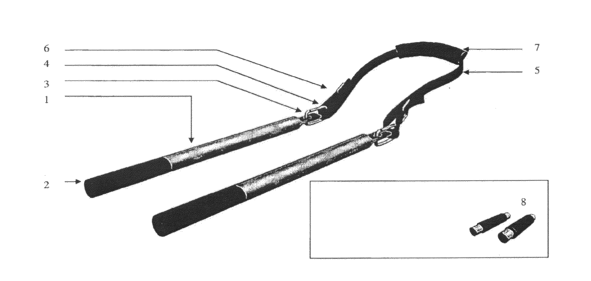
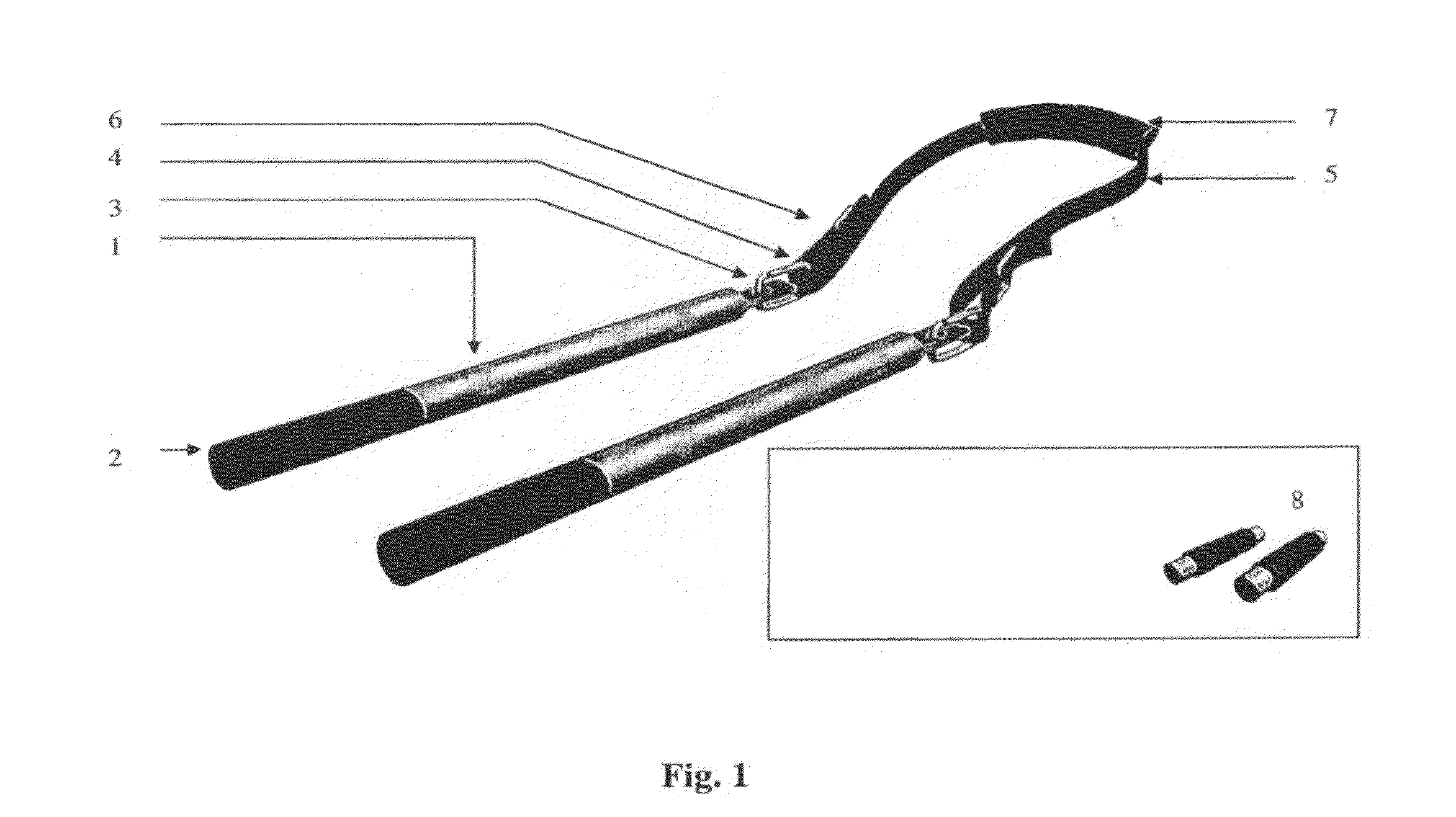
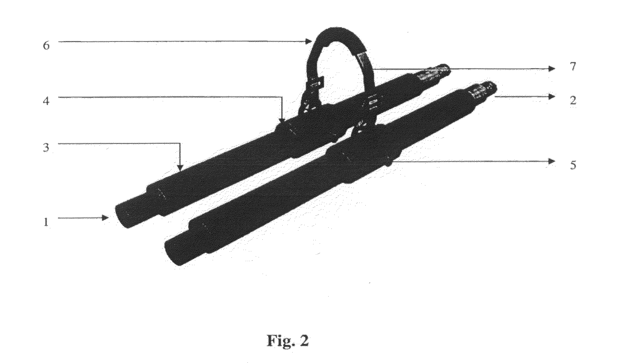
[0014]Further, present invention described in detail refers to attached FIGS. 1, 2, and 3 in which FIG. 1 shows an embodiment of vehicle wheel of assembler of present invention which consists of two directive sticks (1). This has similar design and shape each which consists of directive sticks with inner dredged (2) on its tip. Another tip has hanging hole (3), functions to be hooked (4). Pose a wire belt (5) on each hanging hole of directive sticks such that connect these two directive sticks. A tighter (6) is posed near of hanging hole to adjust its length. A handle is posed on middle of belt which is hollow-pipe shaped like cartridge (7). It is penetrated by said belt so that said handle slides along belt easily.

[0015]FIG. 3 shows instruction to utilize wheel assembler of present invention, it is to put desired wheel (8) near wheel drum (9). Take distance around 10-15 cm, penetrate two directive sticks into two holes on rim. Preferred start from most upper hole and second one. Th...


PUM

PropertyMeasurementUnit
Lengthaaaaaaaaaa
Flexibilityaaaaaaaaaa

Abstract

The vehicle wheel assembler of the present invention consists of two directive sticks (1) with similar design and shape which each stick consists of an inner dredge (2) on one end of the tip. On the other end of the stick a hanginge hole (3) is provided to be hooked with a wire belt (5) in order to connect these two directive sticks. A tighter (6) is posed near the hanging hole to adjust the length of the belt. A handle (7) is posed on the middle of the belt which is a hollow-pipe shaped cartridge. The handle (7) is penetrated by said belt (5) so that it slides along said belt easily. To provide present invention to another system, an adaptor (8) with outer dredge on both tip is used.

Description

TECHNICAL FIELD[0001]Present invention relates to a device to assemble wheel of vehicle consists of set of tools to ease wheel installation to a vehicle (such as sedan, truck, tractor, etc).BACKGROUND ART[0002]Conventional wheel assembly has some obstacles, fitting bolts into car's rim in particular, which are located in drum of wheel (hub). This is caused by drum of wheel needs three-directions of movement at once, i.e. 1) leveraging big and heavy wheel, 2) fitting relatively small of rim into bolts located in drum of wheel, 3) pushing said wheel to its drum ward. These become harder while in a dark place. Using present invention, those conventional technique's defects will be solved quickly and easily.SUMMARY OF INVENTION[0003]In order to embody present invention, it inserts two directive sticks into most upper hole and its neighbor on the rim so that penetrated, thus install dredged stick into such bolts on wheel drum (advised that to align those directive sticks with bolts of wh...

Claims


Application Information

Patent Timeline
IPC IPC(8): B60B29/00
CPCY10T29/53922B60B29/001
Inventor SUGITO, SRI URIPTO
Owner SUGITO SRI URIPTO
Why Eureka
Try Eureka