Funnel structure for oil case

a funnel and oil case technology, applied in the direction of liquid handling, packaging, transportation and packaging, etc., can solve the problems of reducing the life of the gear train, increasing the risk of failure or malfunction of the automobile, and gradually losing the viscosity of the oil used in this way, so as to facilitate the replacement of oil and achieve the effect of convenient and convenient oil replacement and tightness

Inactive Publication Date: 2012-10-25
LIH YANN INDAL
View PDF13 Cites 18 Cited by
  • Summary
  • Abstract
  • Description
  • Claims
  • Application Information

AI Technical Summary

Benefits of technology

[0009]A primary objective of the present invention is to provide a funnel structure for use in an oil case, wherein the funnel structure allows of adjustability through selective use of an extender and / or a coupler to accord to the locations of various oil cases and mating with an oil feeding port of oil cases of different specifications by selective and alternative use of a conic cap, so as to ensure convenience and ease of oil replacing and tightness.
[0010]Another objective of the present invention is to provide a funnel structure for use in an oil case, which comprises a funnel body having a top surface that is made inclining at a predetermined slope and having a circumferential wall forming opposite cut-offs for helping stabilizing an oil bottle in an up-side-down fashion for pouring oil.
[0011]A further objective of the present invention is to provide a funnel structure for use in an oil case, which comprises a conic cap that has a bottom end forming a round tube having an outer circumferential surface forming opposite projections, which mates inward-projecting flanges and notches forming inside an oil feeding port of an oil case for secure retention of the funnel in the oil feeding port.

Problems solved by technology

If not being properly taken care of, the gears are susceptible to generation high temperature, which reduces the life span of the gear train and increases risk of failure or malfunctioning of the automobile.
The oil that is used in this way will gradually loss viscosity and thus the lubricity thereof during the use thereof.
Consequently, when such a diameter-reduced stem 72 is inserted into an oil feeding port 50 of an oil case that has a large bore diameter, the stem cannot be properly supported in an erected condition and thus shows an instable condition, easily leading to tipping and unsecured retention in position.
This is a major drawback of the conventional funnel in this application.
Further, the conventional funnel 70 is of a fixed height, which is not adjustable to accord to the location of the oil feeding port 50 of oil case, making it inconvenient in use.
This is adverse for positioning an oil bottle thereon in an up-side-down fashion, making the oil bottle instable in feeding oil into the oil case and the oil bottle must be held by a hand.
This is inconvenient in use.

Method used


Image

  • Funnel structure for oil case
  • Funnel structure for oil case
  • Funnel structure for oil case

Examples


Embodiment Construction

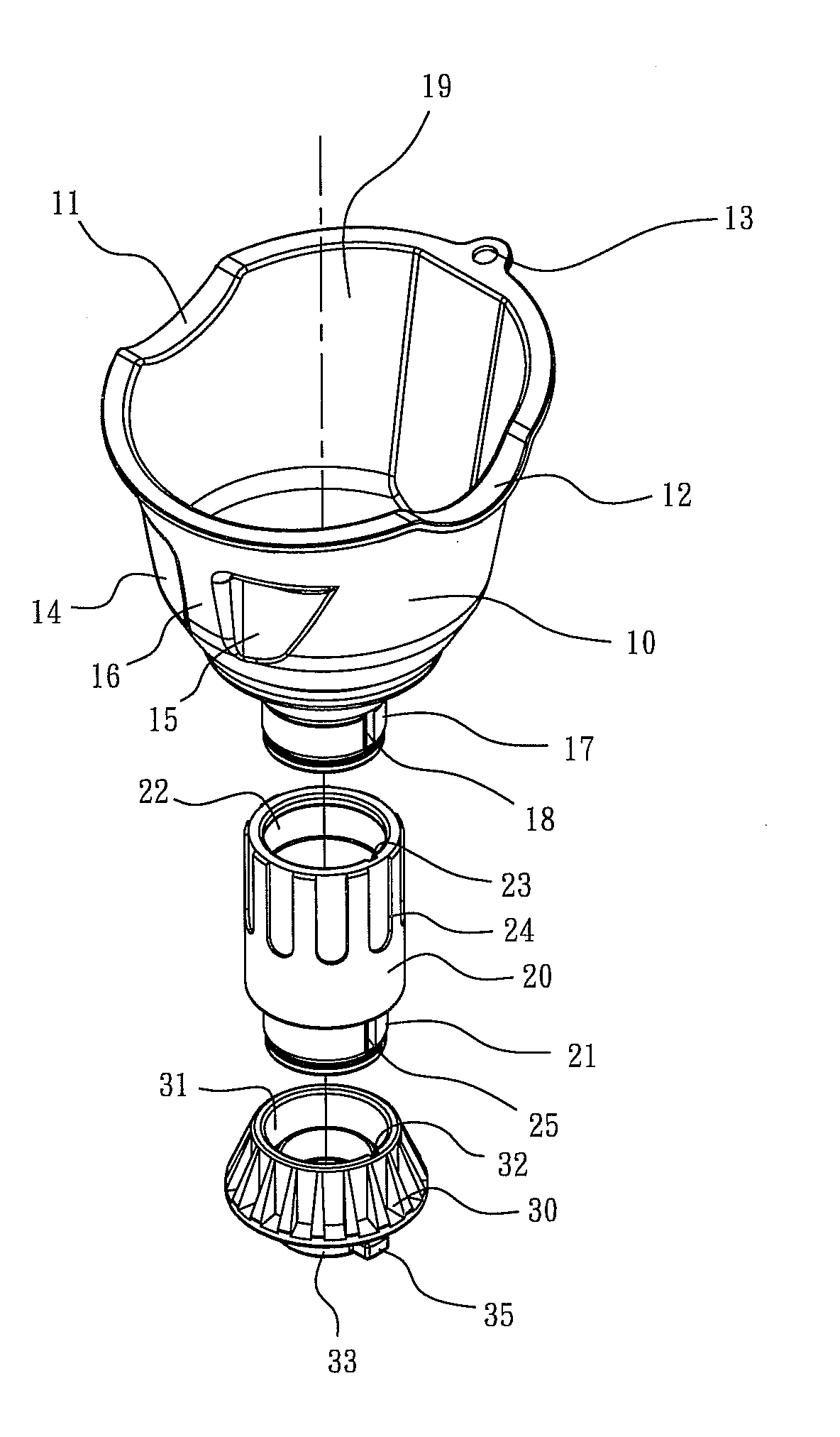
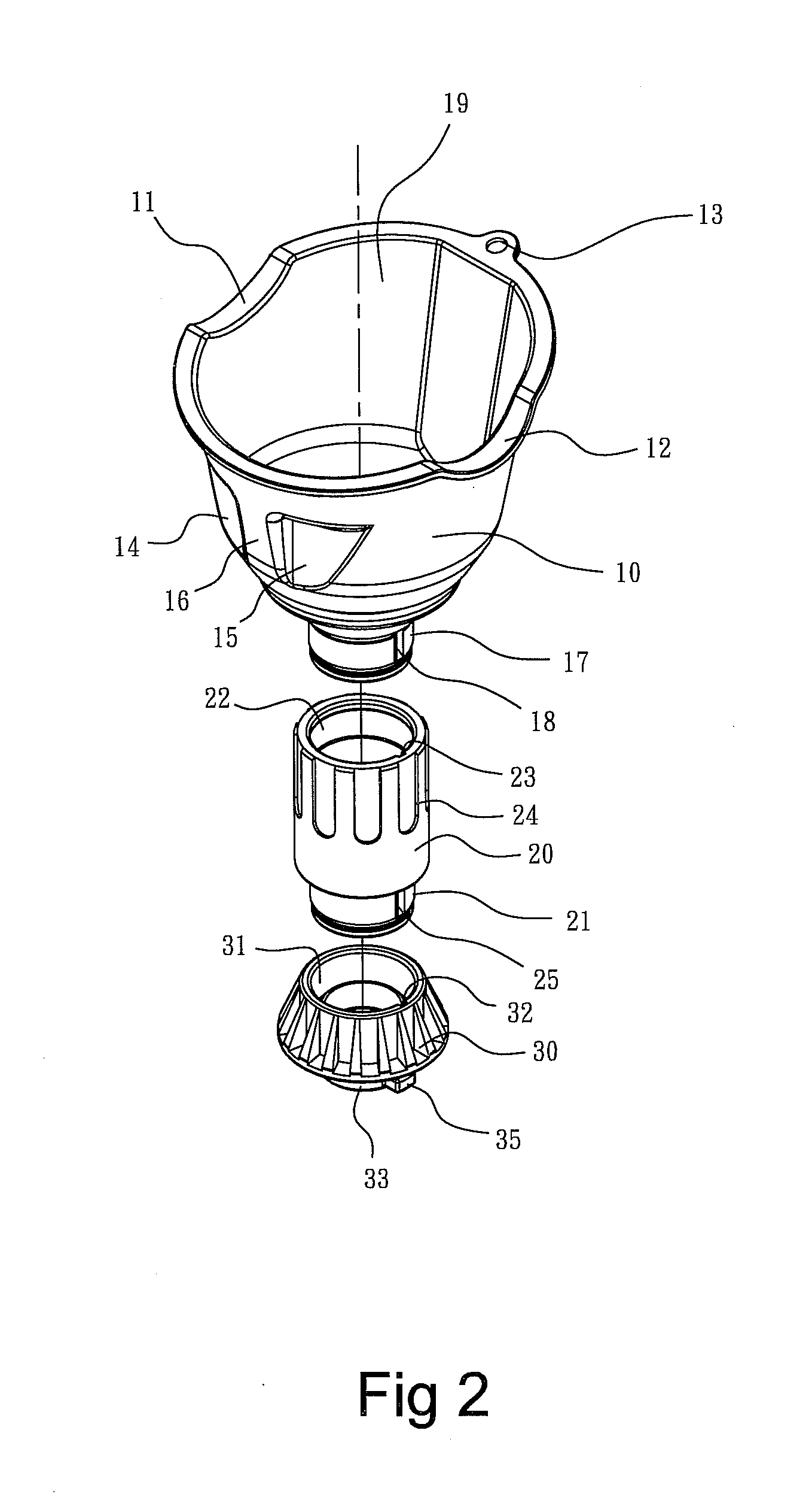
[0021]With reference to the drawings and in particular to FIGS. 2-4, which are respectively an exploded view, a cross-sectional view, and a perspective view of a funnel structure according to an embodiment of the present invention for use in an oil case. The funnel structure of the present invention comprises generally a funnel body 10, an extender 20, and a conic cap 30, which will be described in the following.

[0022]The funnel body 10 is a hollow member receiving and retaining therein a filter mesh 101 for filtering off foreign objects entraining oil poured therein. The funnel body 10 has a top end surface, which is made inclining at a predetermined slope. The top surface has a circumferential wall that is recessed at opposite portions to form two opposite cut-offs 11, 12. The two cut-offs 11, 12 help ensuring stability of locating the oil bottle 60 (see FIG. 6) in an up-side-down condition for pouring oil. The funnel body 10 also forms a hanger hole 13. The funnel body 10 has a c...


PUM


Abstract

A funnel structure includes a funnel body, which has a top surface made inclining at a predetermined slope and a circumferential wall forming opposite cut-offs for stably holding an oil bottle that pours oil into an oil case and has a bottom end forming a joint tube and a first key, an extender, which has a top end forming a first joint bore and a first keyway for receiving and jointing the first joint tube and the first key and a bottom end forming a second joint tube and a second key, and a conic cap, which forms a second joint bore and a second keyway for receiving and jointing the second joint tube and the second key. The conic cap has a bottom end forming a round tube and two opposite projections to mate inward-projecting flanges and notches forming in an oil feeding port of the oil.

Description

BACKGROUND OF THE INVENTION[0001]1. Field of the Invention[0002]The present invention relates to the field of funnel for use in an oil case, and in particular to an oil case funnel that is of a structure allowing of altitude adjustability according to the location of the oil case and secure retention on an oil feeding port of the oil case.[0003]2. The Related Arts[0004]An automobile comprises a train of meshed gears among which friction is induced in the transmission of power. If not being properly taken care of, the gears are susceptible to generation high temperature, which reduces the life span of the gear train and increases risk of failure or malfunctioning of the automobile. Thus, it is often to supply a suitable amount of oil to the site of the gear train for lubrication and reduction of friction among the gears. The oil that is used in this way will gradually loss viscosity and thus the lubricity thereof during the use thereof. The oil must be replaced periodically. Replacin...

Claims


Application Information

Patent Timeline
Patent Type & Authority Applications(United States)
IPC IPC(8): B67C11/02
CPCB67C2011/027B67C11/02
Inventor LIAO, PO-LIN
Owner LIH YANN INDAL
Why Eureka
Try Eureka