
Antenna device for a portable terminal

Active Publication Date: 2012-10-25
SAMSUNG ELECTRONICS CO LTD
View PDF5 Cites 60 Cited by
  • Summary
  • Abstract
  • Description
  • Claims
  • Application Information

AI Technical Summary

Benefits of technology

[0010]An aspect of the present invention is to solve at least the above-mentioned problems and / or disadvantages and to provide at least the advantages described below. Accordingly, an aspect of the present invention is to provide an antenna device for a portable terminal, for allowing a metal body which is mounted on a case frame not to degrade antenna performance.
[0011]Another aspect of the present invention is to provide an antenna device capable of enhancing antenna performance for a portable terminal, using a metal body that is mounted on a case frame.

Problems solved by technology

Thus, it is becoming more and more difficult to mount a plurality of components in the limited space of the portable terminal as the portable terminal is being reduced in size.
However, it is becoming increasingly more difficult to implement an antenna with a desired performance in the limited space of the latest generation portable terminals.
This metal body results in a degradation of antenna performance.

Method used


Image

  • Antenna device for a portable terminal
  • Antenna device for a portable terminal
  • Antenna device for a portable terminal

Examples


first embodiment

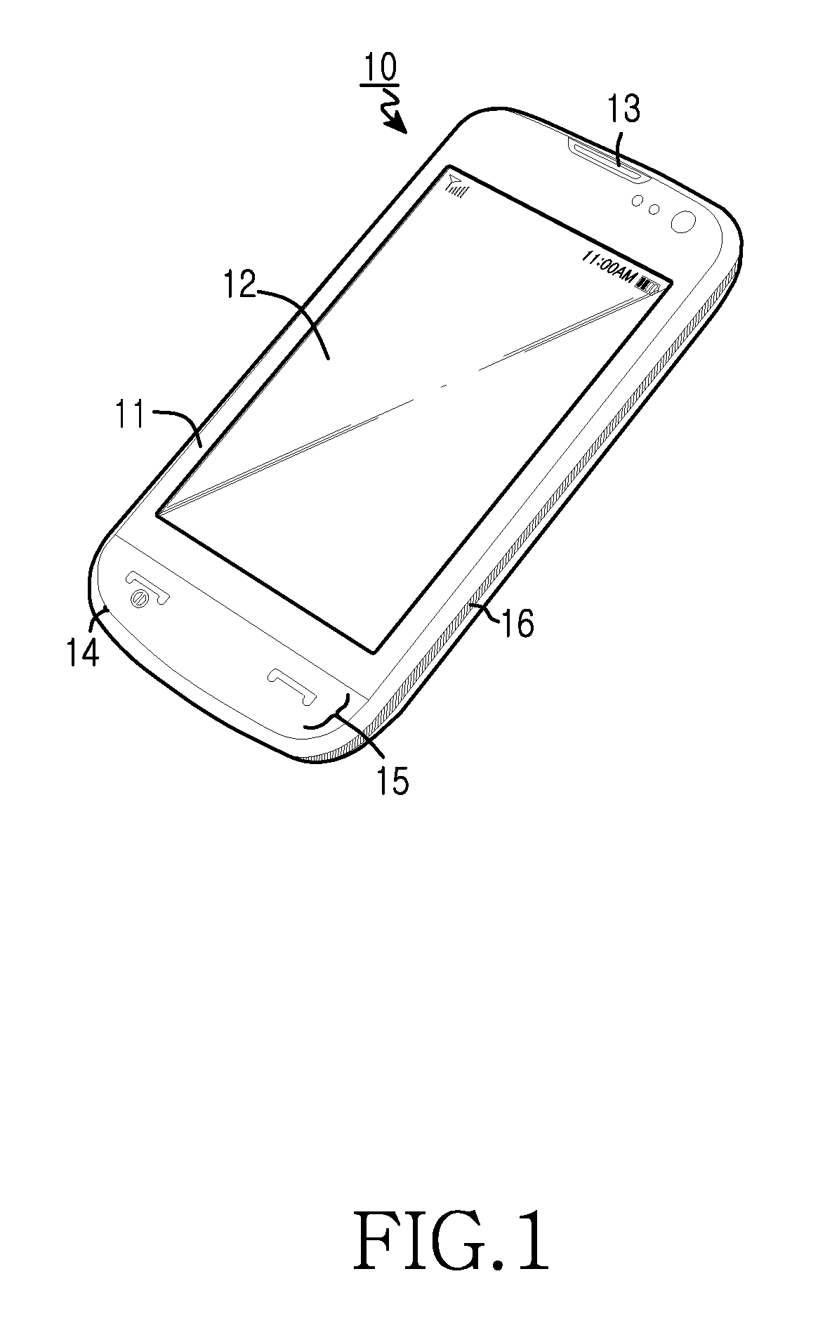
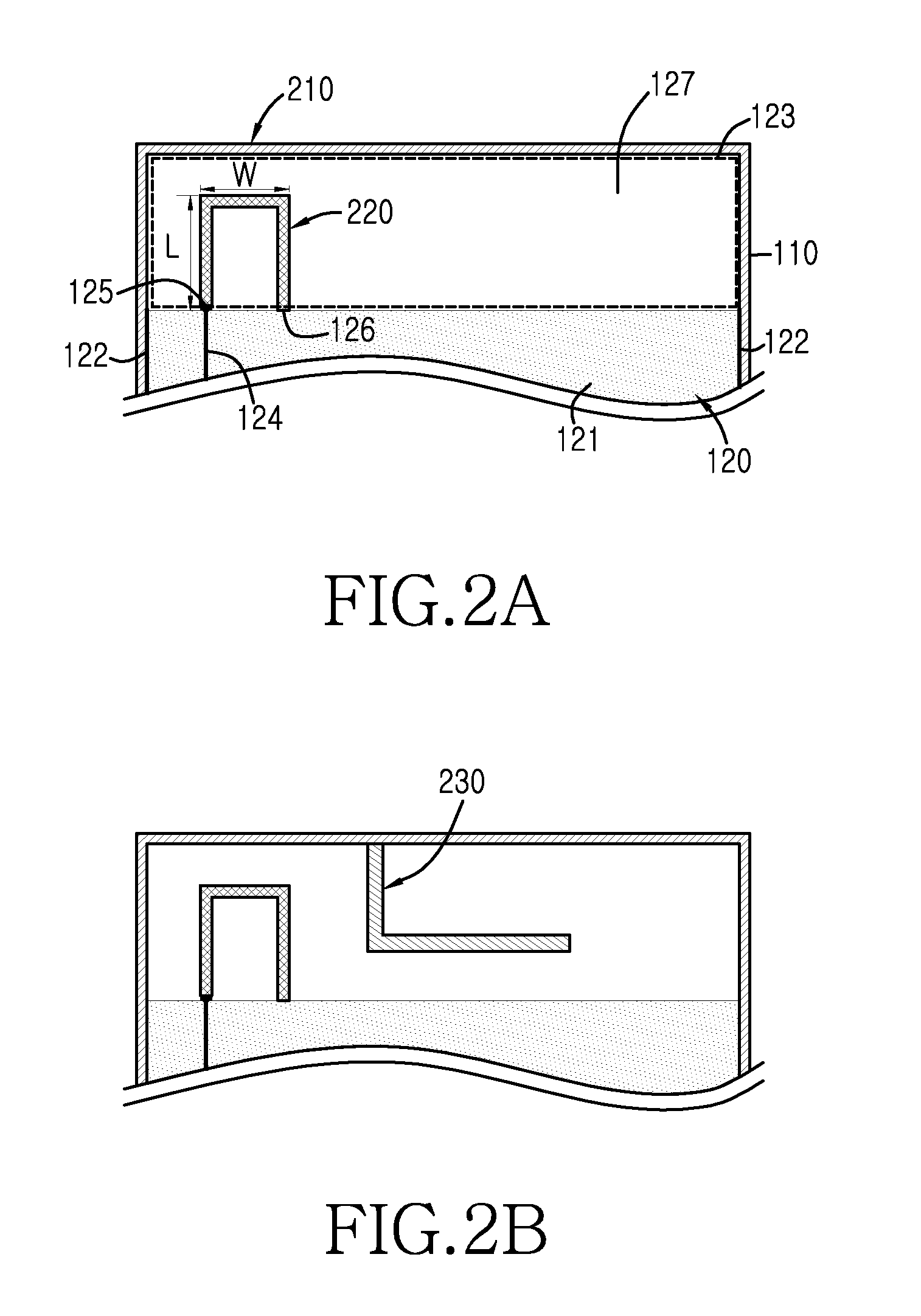
[0031]An antenna device according to the present invention for reducing the interference caused by the metal edge has the following composition; a slot radiator equipped with the metal edge 16 and a ground surface of a main board. In addition, the antenna device according to an embodiment of the present invention includes a loop radiator for magnetically coupling with the slot radiator. The loop radiator receives power from the main board and radiates radio waves. The slot radiator is magnetically coupled by the radiation generated by the loop radiator. Also, the antenna device according to an embodiment of the present invention may further include a stub for antenna matching.

[0032]FIGS. 2A and 2B illustrate structures for an antenna device incorporated into a portable terminal according to one embodiment of the present invention.

[0033]FIG. 2A represents a top view of an antenna device for a portable terminal according to a first embodiment of the present invention that includes a s...

second embodiment

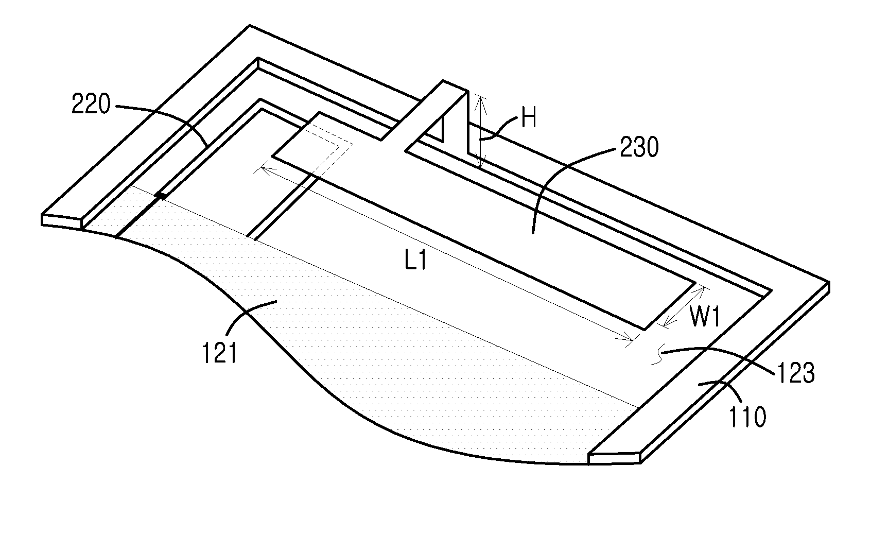
[0050]FIGS. 7B and 7C represent perspective views of an antenna device for a portable terminal according to the present invention.

[0051]FIG. 7B illustrates an antenna device for the portable terminal similar to that shown in FIG. 2A. As previously discussed, the slot radiator 210 is magnetically coupled by the loop radiator 220. A detailed description for the slot radiator 210 and the loop radiator 220 will be omitted as a description of the slot radiator 210 and loop radiator 220 have been presented with reference to FIG. 2A and need not be presented again herein.

[0052]FIG. 7C is a perspective view of an antenna device for a portable terminal according to a second embodiment of the present invention.

[0053]The antenna device shown in FIG. 7C has a structure in which the radiator plate 630 of FIG. 7A and the antenna device of FIG. 7B are integrated.

[0054]FIG. 7C illustrates an antenna device for the portable terminal according to a second embodiment of the present invention that incl...


PUM


Abstract

An antenna device for improving antenna performance of a portable terminal having a metal edge installed on a case frame is disclosed. The antenna device includes a main board equipped with a power supply end for supplying power and a ground surface for grounding the main board, a loop radiator connected with the power supply end of the main board at first end and connected with the ground surface of the main board at a second end, and a metal body disposed along an edge of the portable terminal and electrically connected with the ground surface of the main board.

Description

CLAIM OF PRIORITY[0001]This application claims, pursuant to 35 USC §119, priority to, and the benefit of the earlier filing date of, that patent application filed in the Korean Intellectual Property Office on Apr. 22, 2011 and assigned Serial No. 10-2011-0037897, the entire disclosure of which is incorporated by reference, herein.BACKGROUND OF THE INVENTION[0002]1. Field of the Invention[0003]The present invention relates to the field of portable terminals and more particularly to an antenna device for improved performance.[0004]2. Description of the Related Art[0005]Portable terminals, such as mobile communication terminals (e.g., cellular phones), electronic schedulers, and personal complex terminals have developed into an important means of information transmission. With the rapid expansion of wireless communications, mobile communication terminals have expanded their field of operation to provide not only voice communication but also data communication (e.g., text) and internet ...

Claims


Application Information

Patent Timeline
IPC IPC(8): H01Q1/24H01Q9/04
CPCH01Q1/243H01Q1/48H01Q5/0055H01Q7/00H01Q5/378H01Q9/42H01Q13/10H01Q5/364H01Q9/0421H01Q1/24H01Q1/46
Inventor KIM, JAE-HEELEE, DONG-HYUNPARK, SE-HYUNKIM, AUSTINBYUN, JOON-HO
Owner SAMSUNG ELECTRONICS CO LTD
Learn More