
Device of Floating Wind Turbine Capable of Counterbalancing Torques Therein

a technology of counterbalancing torque and wind turbine, which is applied in the direction of machines/engines, vessel construction, marine propulsion, etc., can solve the problems of not solving the problem of more difficult installation of wind turbines

Inactive Publication Date: 2012-10-25
HOULY
View PDF19 Cites 11 Cited by
  • Summary
  • Abstract
  • Description
  • Claims
  • Application Information

AI Technical Summary

Benefits of technology

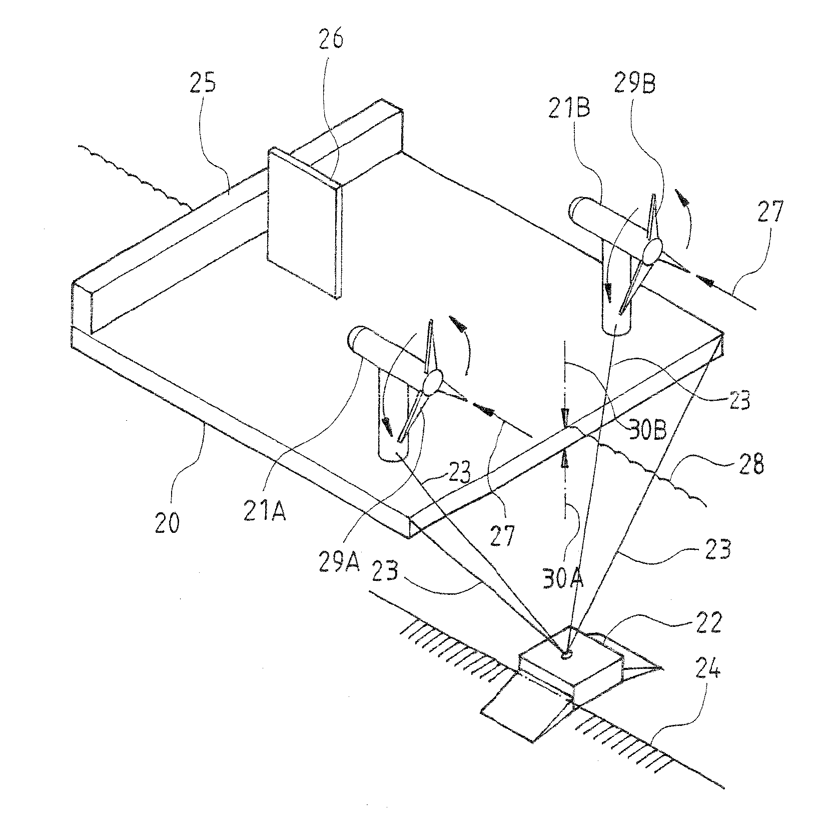
[0005]The primary object is to provide a device of floating wind turbine capable of counterbalancing torques therein, wherein two horizontal-axis wind turbines are symmetrically provided on a floating foundation. Due to both turbines having an approximately equal speed and output power, the torques exerted by the two wind turbines can be counterbalanced and thus the wind turbines and the floating foundation can maintain a balance.
[0006]The aforementioned device comprises a floating foundation, wind turbines provided on the floating foundation, and a seabed anchor attached to the floating foundation, wherein the floating foundation is symmetrically provided with two wind turbines; the floating foundation and the wind turbines are secured to a seabed anchor by tethers. When the wind turbines are driven to generate electrical power, the wind turbines respectively exert an upward force and a downward force at a central portion of the floating foundation between the two wind turbines. Due to both turbines having an approximately equal speed and output power, as long as the floating foundation is robust enough to bear the forces exerted by the wind turbines, the upward force can be counterbalanced by the downward force. Therefore, the wind turbines and the floating foundation can be maintained at a balanced condition.

Problems solved by technology

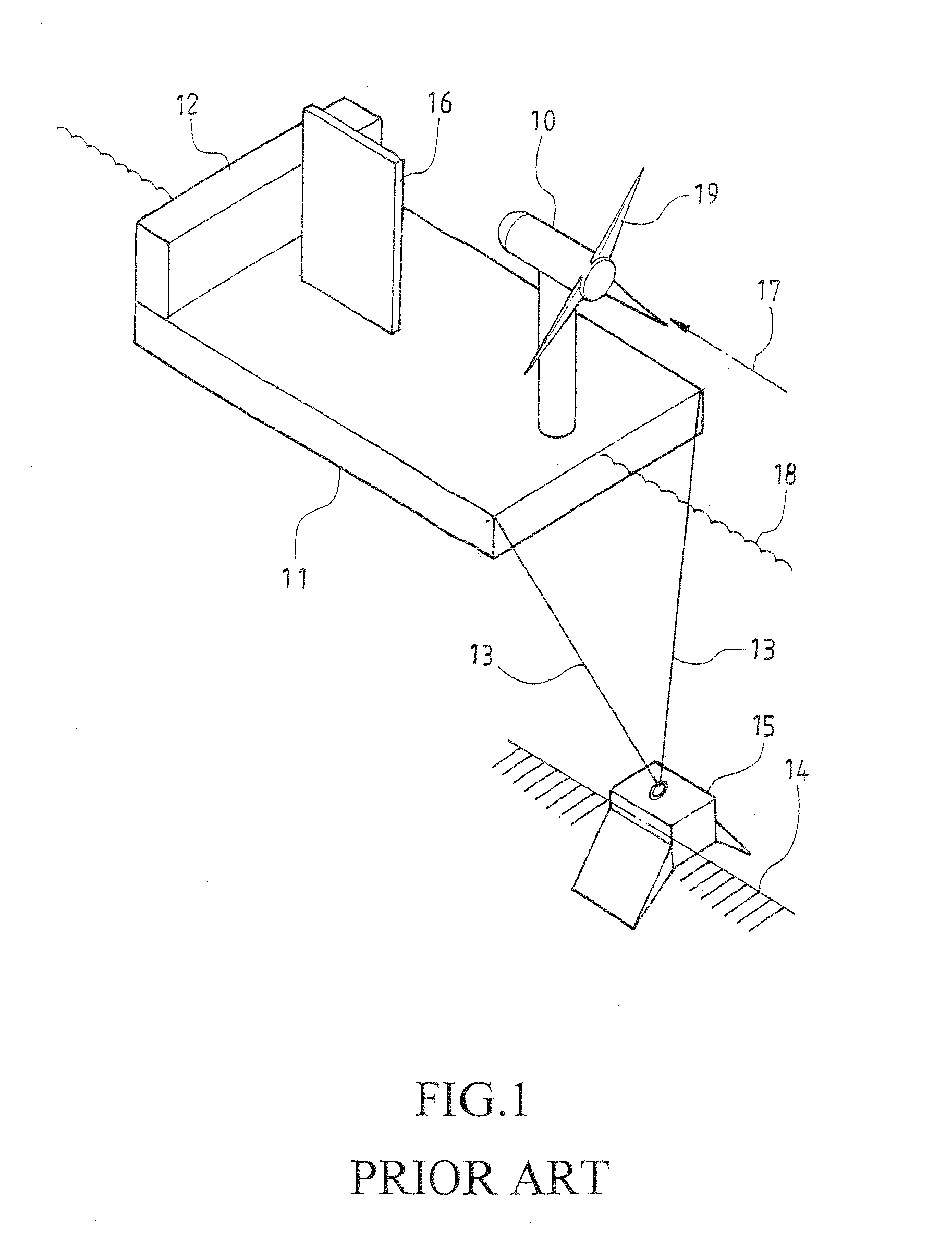
Due to the high cost of land and the fact that the wind is stronger and steadier on the sea, wind turbines are gradually installed in offshore area.
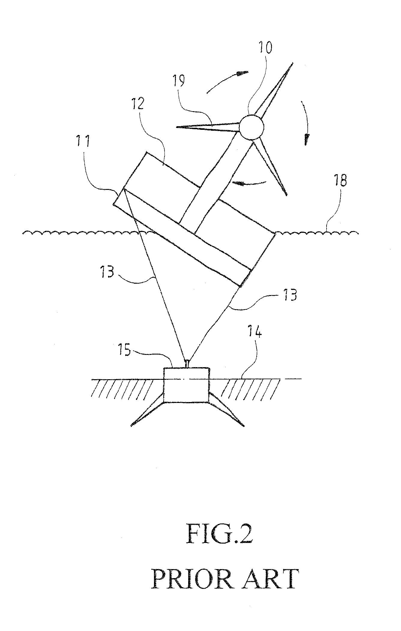
However, if the water depth is more than 35 m, it will be more difficult to install a wind turbine.
However, there is a problem making it infeasible.
So far, the problem is not solved.

Method used


Image

  • Device of Floating Wind Turbine Capable of Counterbalancing Torques Therein
  • Device of Floating Wind Turbine Capable of Counterbalancing Torques Therein
  • Device of Floating Wind Turbine Capable of Counterbalancing Torques Therein

Examples


Embodiment Construction

[0013]FIGS. 3 and 4 respectively show a construction view and a front view of one embodiment of the present invention. As shown, the present invention comprises a floating foundation 20, two wind turbines 21A, 21B symmetrically provided on the floating foundation 20, and a seabed anchor 22 attached to the floating foundation 20. In this embodiment, the two wind turbines 21A, 21B each can be a horizontal-axis or vertical-axis wind turbine, and furthermore, the two wind turbines 21A, 21B each can be an upwind design or a downwind design, or one of the two wind turbines is an upwind design while the other of the two wind turbines is a downwind design. The floating foundation 20 and the wind turbines 21A, 21B are attached to the seabed anchor 22 by tethers 23, in which the seabed anchor 22 is fixed on the seabed 24. The floating foundation 20 is further provided with a ballast 25 for keeping a balance between the front and the rear of the floating foundation 20, and is further provided ...


PUM


Abstract

A device of floating wind turbine comprises a floating foundation, wind turbines provided on the floating foundation, and a seabed anchor attached to the floating foundation, wherein the floating foundation is symmetrically provided with two wind turbines; the floating foundation and the two wind turbines are attached to the seabed anchor by tethers, whereby when the wind turbines are driven to generate electrical power, they respectively exert an upward force and a downward force at a center portion of the floating foundation between the two wind turbines; both turbines have an approximately equal speed and output power; whereby the upward force can be counterbalanced by the downward force, so that the wind turbines and the floating foundation can be maintained at a balanced condition.

Description

CROSS-REFERENCE TO RELATED APPLICATION[0001]This application is a continuation-in-part of the co-pending patent application Ser. No. 13 / 081,460, owned by the same applicant.TECHNICAL FIELD OF THE INVENTION[0002]The present invention relates to a device of floating wind turbine capable of counterbalancing torques therein and, more particularly, to a device of floating wind generator capable of counterbalancing torques therein, based on two wind turbines being symmetrically provided on a floating foundation, whereby when the two wind turbines are driven to generate electrical power, they respectively exert an upward force and a downward force at a central portion of the floating foundation between the two wind turbines, and due to both turbines having an approximately equal speed and output power, the upward force can be counterbalanced by the downward force and thus the wind turbines and the floating foundation can be maintained at a balanced condition.DESCRIPTION OF THE PRIOR ART[00...

Claims


Application Information

Patent Timeline
IPC IPC(8): F03D11/04F03D1/00
CPCF03D11/045Y02E10/727F05B2240/93F03D13/22F03D13/25B63B21/502Y02E10/72
Inventor LIU, KUO-SHEN
Owner HOULY
Learn More