
Cushioning mechanism for a treadmill

a technology of cushioning mechanism and treadmill, which is applied in the direction of gymnastic exercise, sport apparatus, cardiovascular exercise devices, etc., can solve the problems of not easy for general users to conduct the above-mentioned complicated steps, and significantly impaired service life, and achieves excellent responsiveness, great restoring ability, and high tolerance to replace most of the rubber pads

Inactive Publication Date: 2012-10-25
WANG LEAO
View PDF3 Cites 12 Cited by
  • Summary
  • Abstract
  • Description
  • Claims
  • Application Information

AI Technical Summary

Benefits of technology

[0007]An object of the invention is to provide a cushioning mechanism for a treadmill that employs a metal plate with an excellent responsiveness, a great restoring ability, and a high tolerance to replace most of the rubber pads. Moreover, a hanging device movable with the metal plate is used to absorb the displacement of the metal plate when subject to an external force. In this way, an excellent cushioning effect is achieved. In addition, when the metal plate is required to be replaced, it is only necessary to remove the continuous moving belt for conducting the replacement work. As a result, a convenient replacement is ensured.
[0008]According to the invention, at least one set of the cushioning mechanism is interposed between a base frame and a running board. The cushioning mechanism includes two support hanging pieces, two swing hanging pieces, an arched metal plate. The top surface of the arched metal plate is just in contact with the bottom surface of the running board. When the running board is subject to a downward force and sink, the arched metal plate mounted below will be compressed and expanded externally. The expansion displacement of the arched metal plate is compensated by the swing effect of the swing hanging pieces. When the external force is eliminated, the running board is returned back to its original position by the restoring ability of the arched metal plate so that an expected and optimal cushioning effect is achieved.

Problems solved by technology

That is, their service life will be significantly impaired in case of the prolonged exposure to large pressure.
Therefore, it is not easy for the general users to conduct the above-mentioned complicated steps.

Method used


Image

  • Cushioning mechanism for a treadmill
  • Cushioning mechanism for a treadmill
  • Cushioning mechanism for a treadmill

Examples


Embodiment Construction

[0013]The present invention will now be described in more detail hereinafter with reference to the accompanying drawings that show various embodiments of the invention.

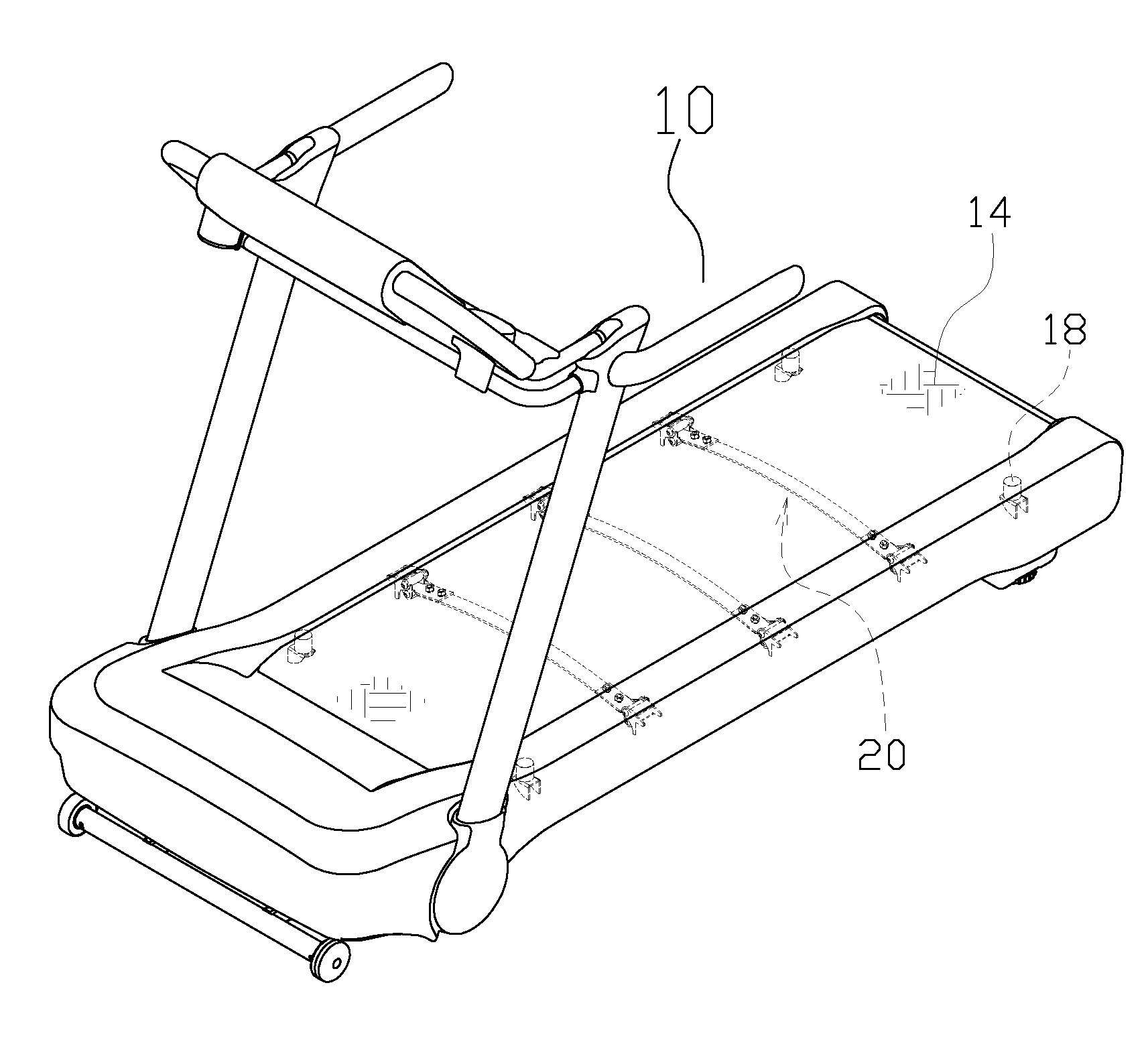
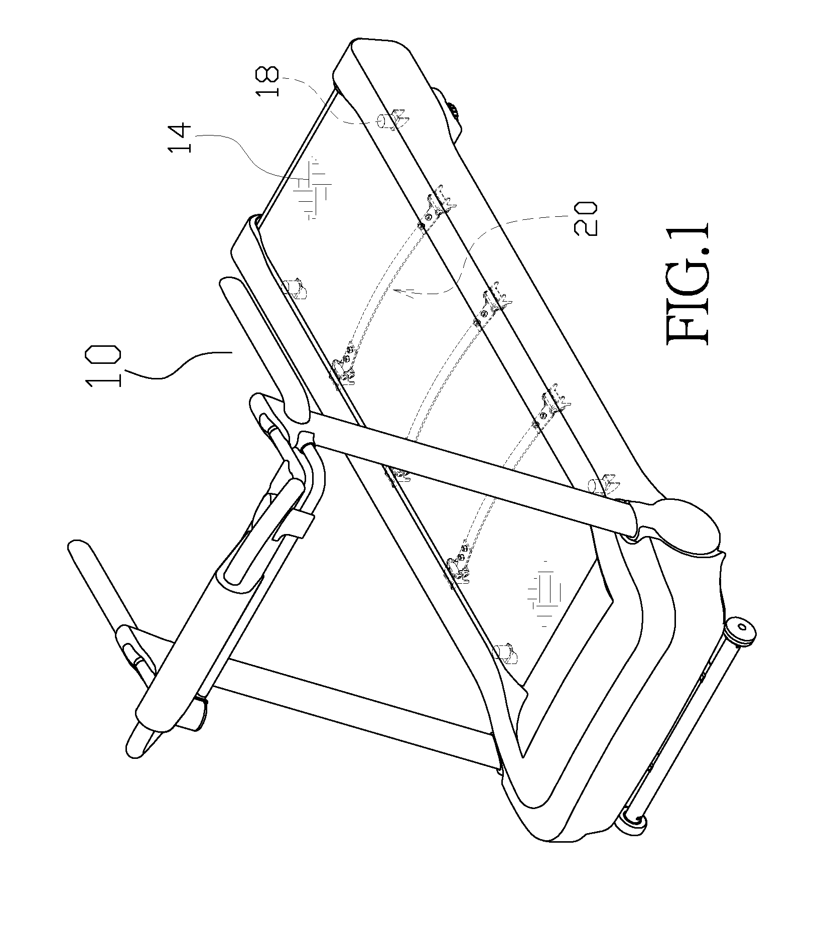
[0014]Referring to FIG. 1, the cushioning mechanism 20 is installed in a hidden way under a running board 12 of the treadmill 10. A continuous moving belt 14 is positioned around the running board 12. The drawing of FIG. 1 is used to illustrate the installation position of the invention.

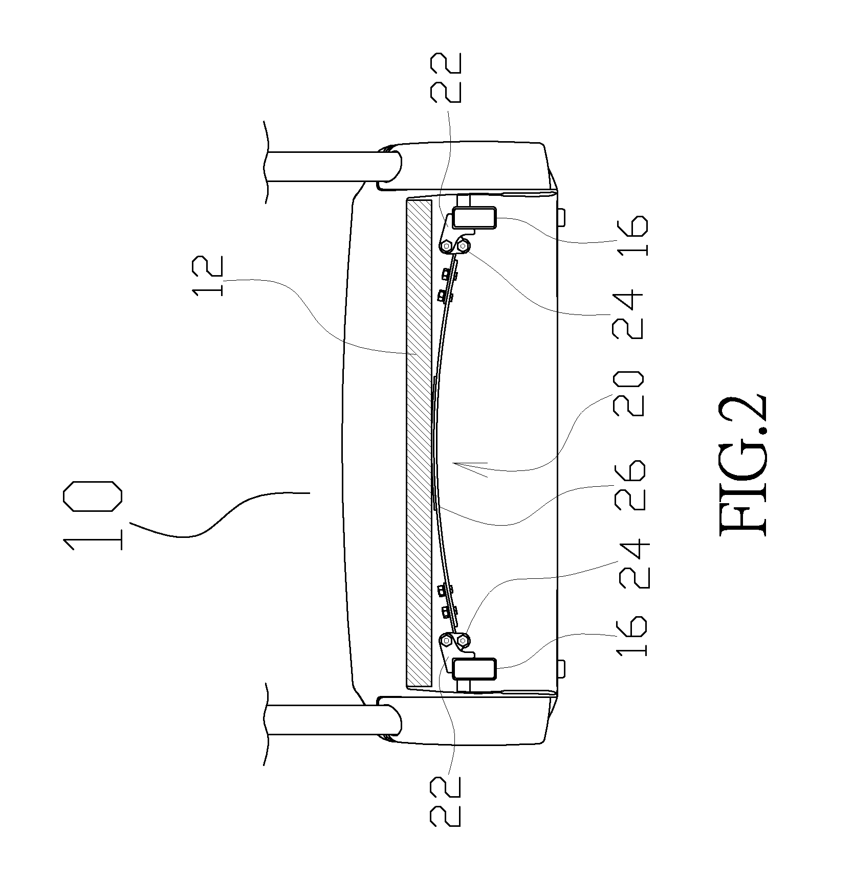
[0015]As shown in FIG. 2, at least one set of the cushioning mechanism 20 is interposed between a base frame 16 and the running board 12. The cushioning mechanism 20 includes two support hanging pieces 22, two swing hanging pieces 24, and an arched metal plate 26.

[0016]The support hanging pieces 22 each have one end fixed at the base frame 16 and the other end pivotably connected to the swing hanging pieces 24.

[0017]The swing hanging pieces 24 are mounted in a hanging way with the bottom end pivotably connected to the arched metal plat...


PUM


Abstract

A cushioning mechanism for a treadmill, wherein at least one set of the cushioning mechanism is interposed between a base frame and a running board, and wherein the cushioning mechanism includes two support hanging pieces, two swing hanging pieces, and an arched metal plate, and wherein the top surface of the arched metal plate is just in contact with the bottom surface of the running board. When the running board is subject to a downward force and sink, the arched metal plate mounted below will be compressed and expanded externally. The expansion displacement of the arched metal plate is compensated by the swing effect of the swing hanging pieces. When the external force is eliminated, the running board is returned back to its original position by the restoring ability of the arched metal plate so that an expected and optimal cushioning effect is achieved.

Description

BACKGROUND OF THE INVENTION[0001]1. Fields of the Invention[0002]The invention relates to a cushioning mechanism for a treadmill, and more particularly, to a structure employing the excellent restoring ability of an arched metal plate in conjunction with a synchronous swing of a hanging device to compensate the expansion displacement for achieving an excellent cushioning effect.[0003]2. Description of the Related Art[0004]It is well-known that the cushioning effect of the conventional treadmills is mostly created by a plurality of rubber pads between the running board and the treadmill's base frame. In this way, these rubber pads provide a certain cushioning effect to properly withstand all reactive forces acting on the treadmill's operator when the running board is subject to an external force.[0005]These rubber pads may produce the cushioning effect to some extent. However, it is an indisputable fact that they can be qualitatively changed due to the environmental and time factors....

Claims


Application Information

Patent Timeline
Patent Type & Authority Applications(United States)
IPC IPC(8): A63B22/02
CPCA63B22/02A63B2022/0214A63B21/026A63B22/0214
Inventor WANG, LEAO
Owner WANG LEAO
Learn More