
Control device for internal combustion engine and method of controlling internal combustion engine

a control device and internal combustion engine technology, applied in the direction of engine starters, electric control, instruments, etc., can solve the problems of large delay (slowness) in restart becoming undesirable to the driver, and long time from the generation of automatic stop requests to the completion of restarting, etc., to reduce the fluctuation in engine rotation speed

Active Publication Date: 2012-10-25
MITSUBISHI ELECTRIC CORP
View PDF6 Cites 12 Cited by
  • Summary
  • Abstract
  • Description
  • Claims
  • Application Information

AI Technical Summary

Benefits of technology

[0019]The present invention has been made to solve the problems described above, and has an object to provide a control device for an internal combustion engine and a method of controlling the internal combustion engine, which are capable of quickly controlling an intake-pipe pressure within a range which allows restartability to be ensured while reducing a fluctuation in engine rotation speed after generation of an automatic stop request and allowing the intake-pipe pressure to be maintained for a longer period of time.
[0023]Therefore, the control device for the internal combustion engine and the method of controlling the internal combustion engine, which are capable of quickly controlling the intake-pipe pressure within the range which allows the restartability to be ensured while reducing the fluctuation in engine rotation speed after the generation of the automatic stop request and allowing the intake-pipe pressure to be maintained for the longer period of time, can be obtained.

Problems solved by technology

In this case, if the starter is energized to crank the engine to restart the engine after the rotation of the engine is completely stopped, time from the generation of the automatic stop request to the completion of the restart becomes long.
As a result, a delay (slowness) in restart becomes undesirably noticeable to the driver.
On the other hand, when the air amount in the cylinders is large, the fluctuation in engine rotation speed becomes large to give a feeling of discomfort due to the vibrations to the driver.
Therefore, an unpleasant noise generated at the time of meshing is unlikely to be noticed by the driver.
On the other hand, when the difference in rotation speed is large, a long time is required to achieve the meshing.
As a result, the unpleasant noise generated at the time of meshing is likely to be noticed by the driver.
Moreover, when the range of variation in the engine rotation speed is large, the difference in rotation speed greatly changes to hardly achieve the meshing.
As a result, the unpleasant noise generated at the time of meshing is likely to be noticed by the driver.
The response delay of an intake system is significantly larger than that of a fuel injection system.
Therefore, even if the fuel injection is restarted immediately in response to the generation of the restart request, the increase in air amount in the cylinders is delayed due to the response delay of the intake system, resulting in a small combustion torque of the engine at the time of restart.
Further, even in the restart of the engine with the starter, the time from the restart to the recovery of the engine rotation speed becomes long.
However, the related art has the following problems.
As a result, the degree of increase in intake-pipe pressure due to the reduction in engine rotation speed becomes relatively large.
Accordingly, although the intake-pipe pressure is desired to be controlled to fall within a given range in order to achieve the conflicting objects described above, the time which allows the given range to be ensured becomes relatively short.
As a result, there is a problem in that the fluctuation in engine rotation speed becomes large.
Therefore, there is another problem in that along time is required for the intake-pipe pressure to reach the range in which the intake-pipe pressure is desired to fall under the control.

Method used


Image

  • Control device for internal combustion engine and method of controlling internal combustion engine
  • Control device for internal combustion engine and method of controlling internal combustion engine
  • Control device for internal combustion engine and method of controlling internal combustion engine

Examples


embodiment 1

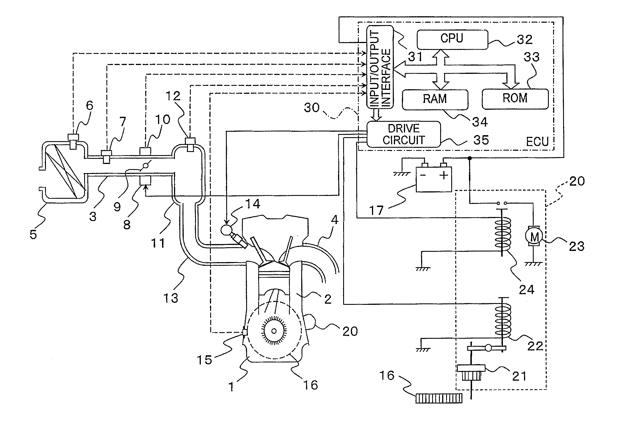
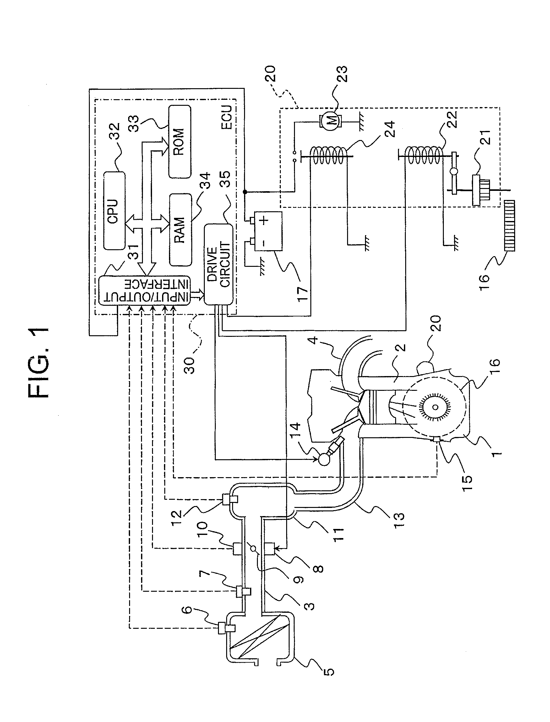
[0034]FIG. 1 is a configuration diagram illustrating an overall system including a control device for an internal combustion engine, according to Embodiment 1 of the present invention. Although a plurality of cylinders 2 are provided to an internal combustion engine 1 (hereinafter, referred to simply as “engine 1”), only one of the cylinders 2 is illustrated in FIG. 1.

[0035]In FIG. 1, an intake pipe 3 and an exhaust pipe 4 are connected to the cylinder 2 of the engine 1. The intake pipe 3 is used to suck air into the cylinder 2. The exhaust pipe 4 is used to exhaust an exhaust gas generated by the combustion of a mixture in a combustion chamber (not shown) of the cylinder 2. On the upstream side of the intake pipe 3, an air filter 5 is provided. An intake-air temperature sensor 6 for detecting a temperature of intake air is mounted to the air filter 5. On the downstream of the air filter 5, an airflow sensor 7 for detecting a flow rate of the intake air (intake air amount) is mounte...


PUM


Abstract

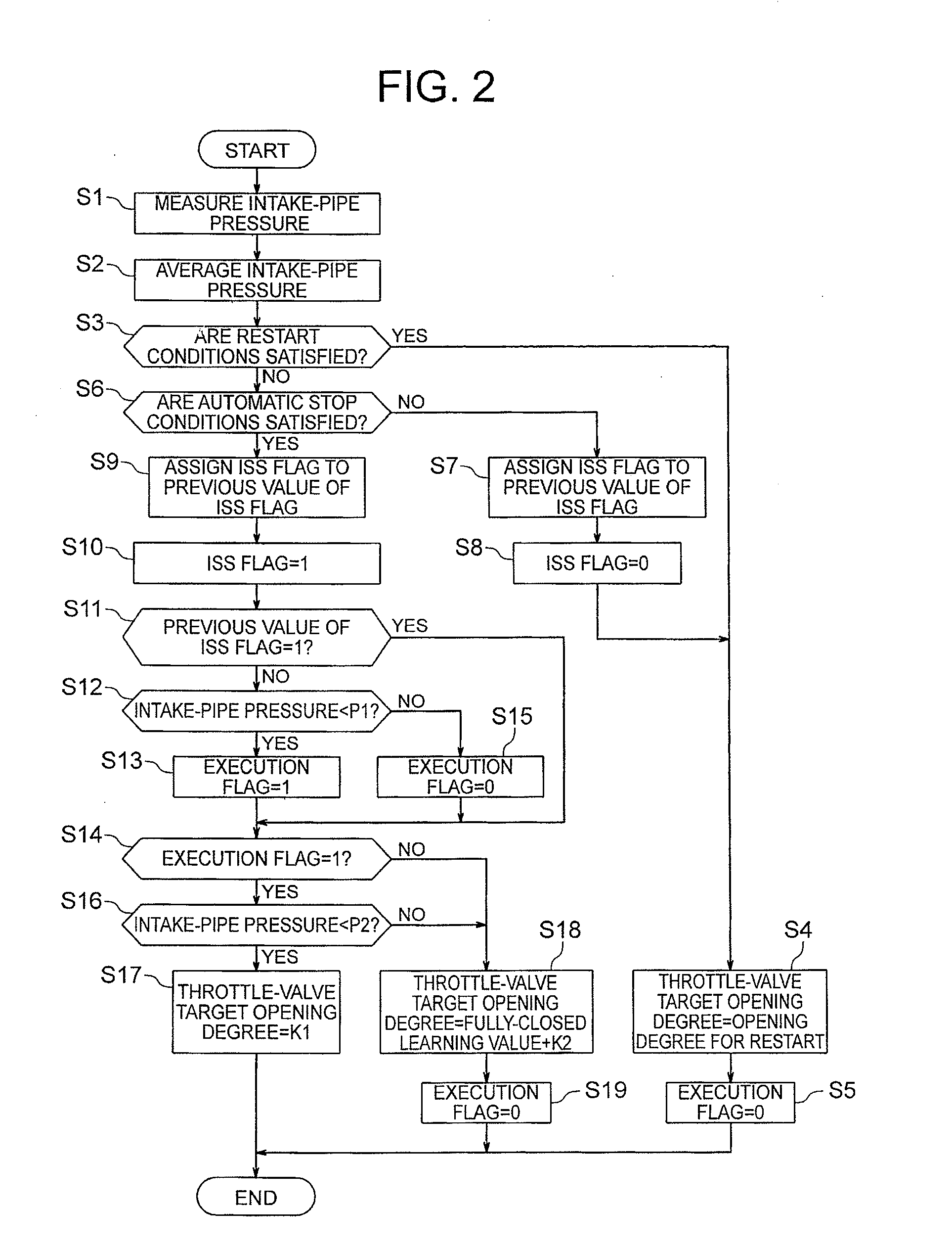
A control device for an internal combustion engine capable of controlling an intake-pipe pressure within a range which allows restartability to be ensured. A control device for an internal combustion engine includes: an idle-stop control section for restarting the engine in response to generation of a restart request; and an intake-air amount control section for setting a control amount of an intake system so that the intake air amount becomes zero when an intake-pipe pressure of the engine upon generation of the automatic stop request is higher than a predetermined pressure and setting the control amount of the intake system so that the intake air amount becomes larger than the amount upon generation of the automatic stop request, and then becomes zero when the intake-pipe pressure is lower than the predetermined pressure.

Description

BACKGROUND OF THE INVENTION[0001]1. Field of the Invention[0002]The present invention relates to a control device for an internal combustion engine (engine) and a method of controlling the internal combustion engine in a vehicle on which an engine automatic stop / start control system (idle-stop control system) for controlling stop and restart of the internal combustion engine is mounted.[0003]2. Description of the Related Art[0004]In recent years, the number of vehicles, on which an engine automatic stop / start control system, so-called idle-stop control system is mounted, is increasing for the purposes of improvement of fuel efficiency and a reduction in gas emission. A general idle-stop control system stops fuel injection (performs fuel-cut) to automatically stop an internal combustion engine (engine) when a driver stops a vehicle. Thereafter, when the driver performs an operation to start the vehicle, for example, a brake-pedal release operation or an accelerator-pedal depressing o...

Claims


Application Information

Patent Timeline
Patent Type & Authority Applications(United States)
IPC IPC(8): F02D41/26F02D41/30F02D28/00
CPCF02D11/10F02D13/0226F02D41/0002F02D41/065Y02T10/42F02N11/0814F02N11/0844F02N99/006Y02T10/48F02D2200/0406Y02T10/40
Inventor OKABE, TAKERUISHIKAWA, OSAMUSHODA, TOMOHISATANI, HIDEAKITANAKA, TORU
Owner MITSUBISHI ELECTRIC CORP
Learn More