
Antenna assembly utilizing metal-dielectric resonant structures for specific absorption rate compliance

a technology of dielectric resonance and antenna assembly, which is applied in the direction of antenna details, slot antennas, antennas, etc., can solve the problems of numerous challenges in antenna design, small and thin devices, and the inability to meet specific absorption rate requirements

Active Publication Date: 2012-11-01
MALIKIE INNOVATIONS LTD
View PDF8 Cites 43 Cited by
  • Summary
  • Abstract
  • Description
  • Claims
  • Application Information

AI Technical Summary

Problems solved by technology

The demand for smaller and thinner devices, present numerous challenges for the antenna design.
Because of the close proximity of the phone to the user, compliance with specific absorption rate (SAR) requirements can be a challenge.
However, the more of the frame that is used, the greater the RF energy that is emitted and thus the specified SAR limit may be exceeded by the data transmission.
As a consequence, in order to comply with the SAR limit, prior communication devices often transmitted with less than an optimal number of transmission slots in each frame and less that the desired signal intensity.

Method used


Image

  • Antenna assembly utilizing metal-dielectric resonant structures for specific absorption rate compliance
  • Antenna assembly utilizing metal-dielectric resonant structures for specific absorption rate compliance
  • Antenna assembly utilizing metal-dielectric resonant structures for specific absorption rate compliance

Examples


Embodiment Construction

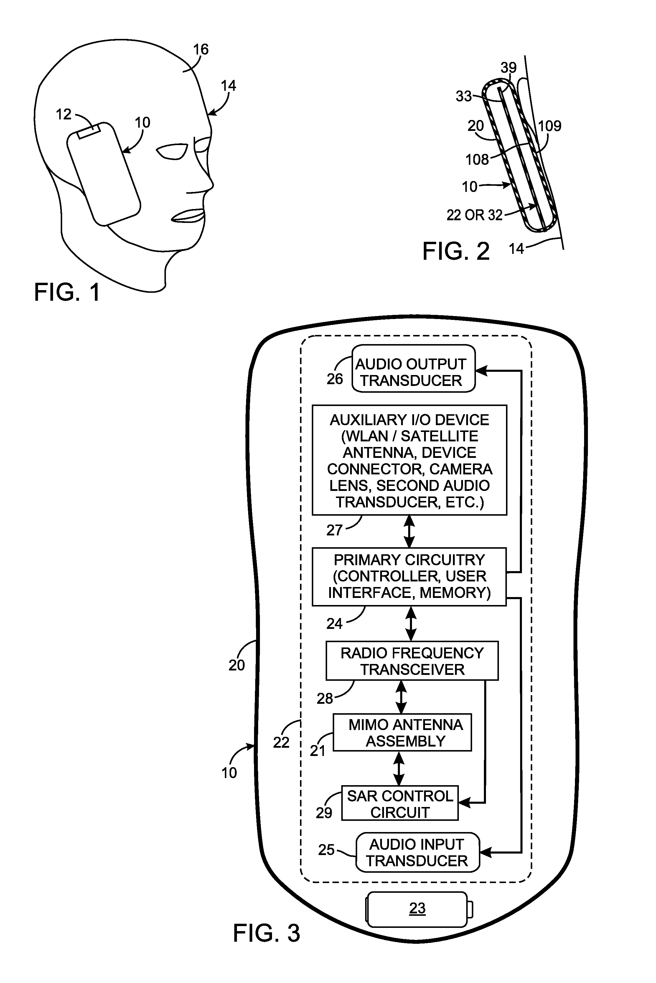
[0018]The disclosure generally relates to a mobile, wireless communication device, examples of which include mobile or handheld devices, such as pagers, cellular telephones, cellular smart-phones, wireless organizers, personal digital assistants, wirelessly enabled notebook computers, and the like.

[0019]A wireless communication device includes an antenna for transmitting a radio frequency (RF) signal. Associated with the antenna are one or more elements that reflect radio frequency energy that is directed towards the user of the communication device. This enables a greater signal intensity and a greater data transmission rate to be used to transmit the RF signal, than otherwise would be possible without the transmission exceeding the specific absorption rate limit.

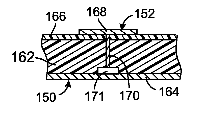
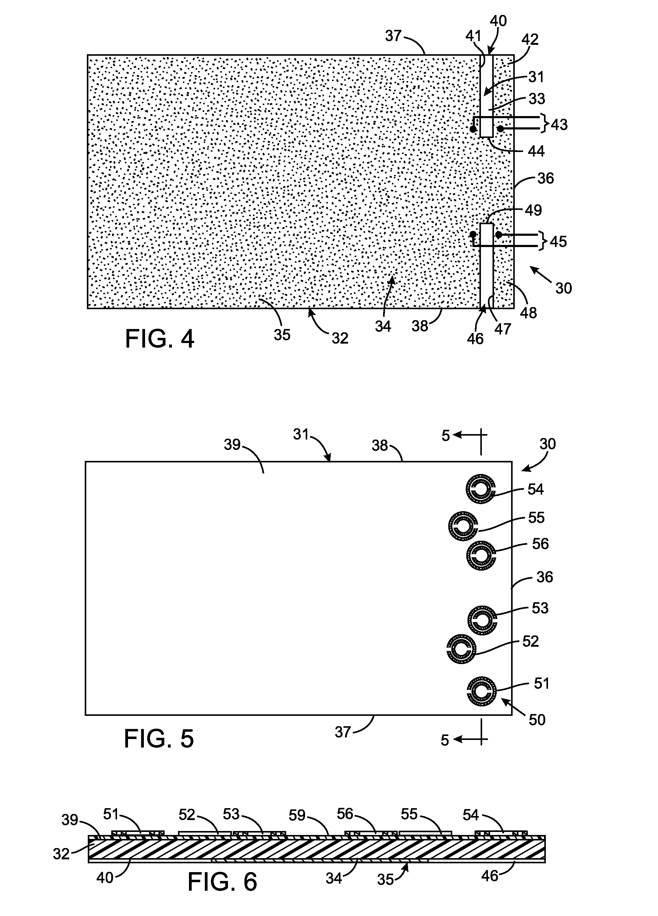
[0020]Each such element comprises a metal-dielectric structure that resonates at a frequency corresponding to the frequency of the signal being transmitted by the wireless communication device. These metal-dielectric struc...


PUM


Abstract

An wireless communication device has a housing with an exterior surface that is designed to face a user when the wireless communication device is transmitting a radio frequency signal. The communication device includes an antenna disposed inside the housing for emitting a radio frequency signal. A metal-dielectric structure resonates to reflect the radio frequency signal. The metal-dielectric structure is located between the antenna and the exterior surface at a position wherein he metal-dielectric structure traps and reflects the radio frequency signal thereby reducing a specific absorption rate of the wireless communication device.

Description

CROSS-REFERENCE TO RELATED APPLICATIONS[0001]Not ApplicableSTATEMENT REGARDING FEDERALLY SPONSORED RESEARCH OR DEVELOPMENT[0002]Not ApplicableBACKGROUND OF THE DISCLOSURE[0003]The present disclosure relates to mobile, wireless communication devices, examples of which include handheld, devices such as cellular telephones, personal digital assistants, wirelessly enabled notebook computers, and the like; and more particularly to controlling the emission of the radio frequency signals transmitted by such wireless communication devices to achieve compliance with governmental regulations regarding a specific absorption rate limit.[0004]A wide variety of types of mobile, wireless communication devices are on the market for communicating voice, data, images, and other forms of information. The demand for smaller and thinner devices, present numerous challenges for the antenna design. The antennas must be designed to fit in a limited available space and support various operating characterist...

Claims


Application Information

Patent Timeline
IPC IPC(8): H01Q19/10H01Q21/00
CPCH01Q1/243H01Q1/521H01Q17/007H01Q17/00H01Q13/10
Inventor AYATOLLAHI, MINA
Owner MALIKIE INNOVATIONS LTD
Learn More