Unlock instant, AI-driven research and patent intelligence for your innovation.

Image encoding device, image decoding device, image encoding method, and image decoding method

a technology of image signal and encoding method, applied in the direction of instruments, electrical appliances, computing, etc., can solve the problem of insufficient prediction efficiency and achieve the effect of improving the accuracy of image signal prediction within a frame according to a conventional method, improving the prediction accuracy and improving the encoding efficiency

Active Publication Date: 2012-11-01
COMCAST CABLE COMM LLC
View PDF1 Cites 9 Cited by
  • Summary
  • Abstract
  • Description
  • Claims
  • Application Information

AI Technical Summary

Benefits of technology

The present invention relates to a technique for encoding and decoding image signals using motion compensation prediction. The invention addresses the problem of low correlation at borders with an encoding target block, which reduces the advantage of prediction and decreases efficiency. The invention proposes a method for generating a prediction signal with high correlation using a displacement vector from an adjacent block and a reference image, thereby increasing the efficiency of the motion compensation prediction process. The invention also addresses the issue of self-similarity and textural similarity of objects in a screen and the difficulty in obtaining a highly accurate displacement vector. The technical effects of the invention are to improve the efficiency and accuracy of image signal encoding and decoding.

Problems solved by technology

However, sufficient prediction efficiency cannot be realized when the amount of transmitting a displacement vector amount is large.

Method used


Image

  • Image encoding device, image decoding device, image encoding method, and image decoding method
  • Image encoding device, image decoding device, image encoding method, and image decoding method
  • Image encoding device, image decoding device, image encoding method, and image decoding method

Examples


first embodiment

[0034]A description is first given of the conformation of an image encoding device and the conformation of an image decoding device according to the first embodiment of the present invention.

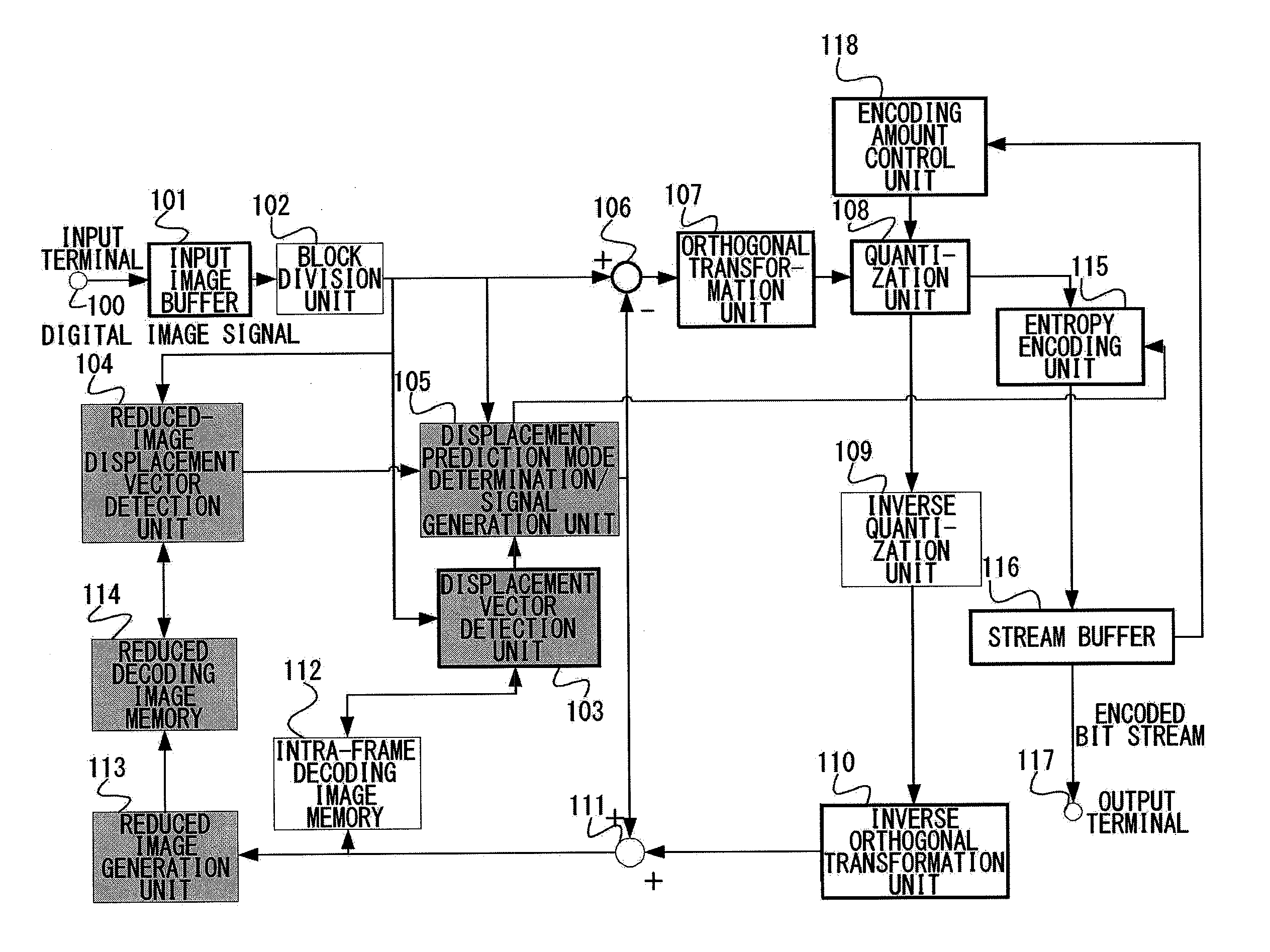
[0035]FIG. 1 is a configuration diagram illustrating the conformation of the image encoding device according to the first embodiment of the present invention. As shown in FIG. 1, the image encoding device according to the present embodiment comprises an input terminal 100, an input image buffer 101, a block division unit 102, a displacement vector detection unit 103, a reduced-image displacement vector detection unit 104, a displacement prediction mode determination / signal generation unit 105, a subtractor 106, an orthogonal transformation unit 107, a quantization unit 108, an inverse quantization unit 109, an inverse orthogonal transformation unit 110, an adder 111, an intra-frame decoding image memory 112, a reduced image generation unit 113, a reduced decoding image memory 114, an entropy enc...

second embodiment

[0073]A description is now given of the conformation of an image encoding device and the conformation of an image decoding device according to a second embodiment of the present invention. The first embodiment is directed to an image encoding or decoding device that uses only correlation within a frame. However, the second embodiment is directed to an image encoding or decoding device, in which the time correlation of a moving image can be utilized, that uses correlation within a frame and correlation between frames.

[0074]FIG. 5 is a configuration diagram illustrating the conformation of the image encoding device according to the second embodiment of the present invention. As shown in FIG. 5, the image encoding device according to the present embodiment comprises an input terminal 100, an input image buffer 101, a block division unit 102, a displacement vector detection unit 103, a reduced-image displacement vector detection unit 104, a displacement prediction mode determination / sig...

third embodiment

[0106]A description is now given of the conformation of an image encoding device according to the third embodiment of the present invention. In the third embodiment, identification of a reduced filter coefficient by frequency analysis is not performed for the configuration according to the second embodiment. However, a configuration is employed where the most appropriate reduction filter coefficient is set and used for encoding and decoding processes by measuring a prediction efficiency that involves displacement of a reduced image and an input image. Therefore, an image decoding device according to the third embodiment can be realized by a configuration that is same as the image decoding device according to the second embodiment. Thus, a description is given regarding only an encoding device.

[0107]FIG. 9 is a configuration diagram illustrating the conformation of the image encoding device according to the third embodiment of the present invention. The configuration of the image enc...


PUM


Abstract

A displacement vector detection unit searches for a signal with high correlation with an encoding target block using a locally-decoded image in an already encoded block so as to calculate, using a signal with the highest correlation as a displacement prediction signal, a displacement vector. A reduced-image displacement vector detection unit searches for a signal with high correlation with the encoding target block using a signal resulting from performing reduction at least either horizontally or vertically for the locally-decoded image in an already encoded block so as to obtain, using the signal with the highest correlation as the displacement prediction signal, the displacement vector indicating the displacement in a screen between a reduced encoding target block and a reduction displacement prediction signal. Then a signal with high correlation with the encoding target block from the displacement prediction signal and the reduction displacement prediction signal is selected as a prediction signal.

Description

TECHNICAL FIELD[0001]The present invention relates to a technique for encoding and decoding image signals and to an image encoding device, an image decoding device, an image encoding method, and an image decoding method in which an in-screen prediction process of generating a prediction signal for a target image signal from an encoded image and then encoding a differential signal between the target image signal and the prediction signal is used.BACKGROUND ART[0002]In recent years, services for distributing digitalized image and audio content via broadcast waves, such as satellite or ground waves, or networks are in practical use, and highly efficient encoding is thus necessary for efficiently recording and transmitting the information of images and sounds that have tremendous amount of information. As content has become finely-resolved and more diverse, the number of images to be encoded and the amount of data have become more increased. Thus, more highly efficient encoding of image...

Claims


Application Information

Patent Timeline
Patent Type & Authority Applications(United States)
IPC IPC(8): G06K9/46H04N19/12H04N19/137H04N19/50H04N19/147H04N19/176H04N19/196H04N19/423H04N19/503H04N19/51H04N19/567H04N19/59H04N19/593H04N19/61H04N19/625H04N19/80H04N19/91
CPCH04N19/52H04N19/53H04N19/593H04N19/46
Inventor UEDA, MOTOHARU
Owner COMCAST CABLE COMM LLC