Automated tuning of gas turbine combustion systems

a technology of automatic tuning and combustion system, which is applied in the direction of adaptive control, instruments, lighting and heating apparatus, etc., can solve the problems of inability to timely change, inability to operate normally, and inability to meet the requirements of the system

Active Publication Date: 2012-11-01
GTE TURBINE EFFICIENCY SWEDEN AB
View PDF2 Cites 40 Cited by
  • Summary
  • Abstract
  • Description
  • Claims
  • Application Information

AI Technical Summary

Benefits of technology

[0014]In a further aspect of the disclosure, the system performs a method for determination of the dominant gas turbine combustion system tuning scenario (dominant tuning concern) through the use of Boolean hierarchical logic and multiple levels of control settings.
[0015]In another aspect of the disclosure, the method performed relates to automated control of the gas turbine inlet fuel temperature through automated modification of the fuel gas temperature control set point within a Distributed Control System (DCS) or similar control system.
[0016]In a still further aspect of the disclosure, a method for automated control of a gas turbine inlet fuel temperature is defined by automated modification of the fuel gas temperature control set point within the fuel gas temperature controller.
[0017]In another aspect of the disclosure a method for communicating turbine control signals to a gas turbine controller is accomplished through the use of an existing gas turbine communication link with an external control device, such as, for example a MODBUS Serial or Ethernet communication protocol port existing on the turbine controller for communication with the Distributed Control System (DCS).
[0018]In a still further aspect of the disclosure a method for modification of a gas turbine combustion system is defined by a series of auto tuning settings via a user interface display, which utilizes Boolean-logic toggle switches to select user-desired optimization criteria. The method is preferably defined by optimization criteria based on Optimum Combustion Dynamics, Optimum NOx Emissions, Optimum Power, Optimum Heat Rate, Optimum CO Emissions, Optimum Heat Recovery Steam Generator (HRSG) Life, Optimum Gas Turbine Fuel Blend Ratio or Optimal Gas Turbine Turndown Capability whereby toggling of this switch changes the magnitude of the combustor dynamics control setting(s).
[0019]In a still further aspect of the disclosure a method for modification of a gas turbine combustion system is defined by real-time adjustment of a series of auto tuning settings via a tuning parameter adjustment interface, whereby the specific turbine control settings can be modified in real-time by the user / operator through modulation of a series of control devices, whereby activation of these control devices is allowed through triggering of the following Boolean-logic toggle switches: Optimum Combustion Dynamics, Optimum NOx Emissions, Optimum Power, Optimum Heat Rate, Optimum CO Emissions, Optimum Heat Recovery Steam Generator (HRSG) Life, Optimum Gas Turbine Fuel Blend Ratio or Optimal Gas Turbine Turndown Capability.

Problems solved by technology

These settings are satisfactory at the time of the setup, but conditions may change when tuning issues arise and cause an unacceptable operation in a matter of hours or days.
Tuning issues are any situation whereby any operational parameters of a system are in excess of acceptable limits.
These approaches do not allow for timely variation, do not take advantage of actual dynamics and emission data or do not modify fuel distribution, fuel temperature and / or other turbine operating parameters.
Sufficient variation in fuel composition will cause a change in the heat release of the lean premixed combustion system.
Such change may lead to emissions excursions, unstable combustion processes, or even blow out of the combustion system.
Pulsations can have sufficient force to destroy the combustion system and dramatically reduce the life of combustion hardware.
Additionally, improper tuning of the combustion system can lead to emission excursions and violate emission permits.
While real-time tuning of a combustion system can provide tremendous operational flexibility and protection for turbine hardware, a combustion system may concurrently experience a number of different operational issues.
Additionally, tuning in response to one concern can make other constraints worse, for example tuning for low NOx can make combustor dynamics worse, tuning for high CO can make NOx worse, etc.

Method used


Image

  • Automated tuning of gas turbine combustion systems
  • Automated tuning of gas turbine combustion systems
  • Automated tuning of gas turbine combustion systems

Examples


Embodiment Construction

[0040]The present disclosure generally relates to systems and methods for tuning the operation of combustion turbines. In the depicted embodiments, the systems and methods relate to automatic tuning of combustion turbines, such as those used for power generation. Persons of ordinary skill in the art will appreciate that the teachings herein can be readily adapted to other types of combustion turbines. Accordingly, the terms used herein are not intended to be limiting of the embodiments of the present invention. Instead, it will be understood that the embodiments of the present disclosure relate generally to the field of combustion turbines, and in particular for systems, methods and computer readable media for tuning of combustion turbines.

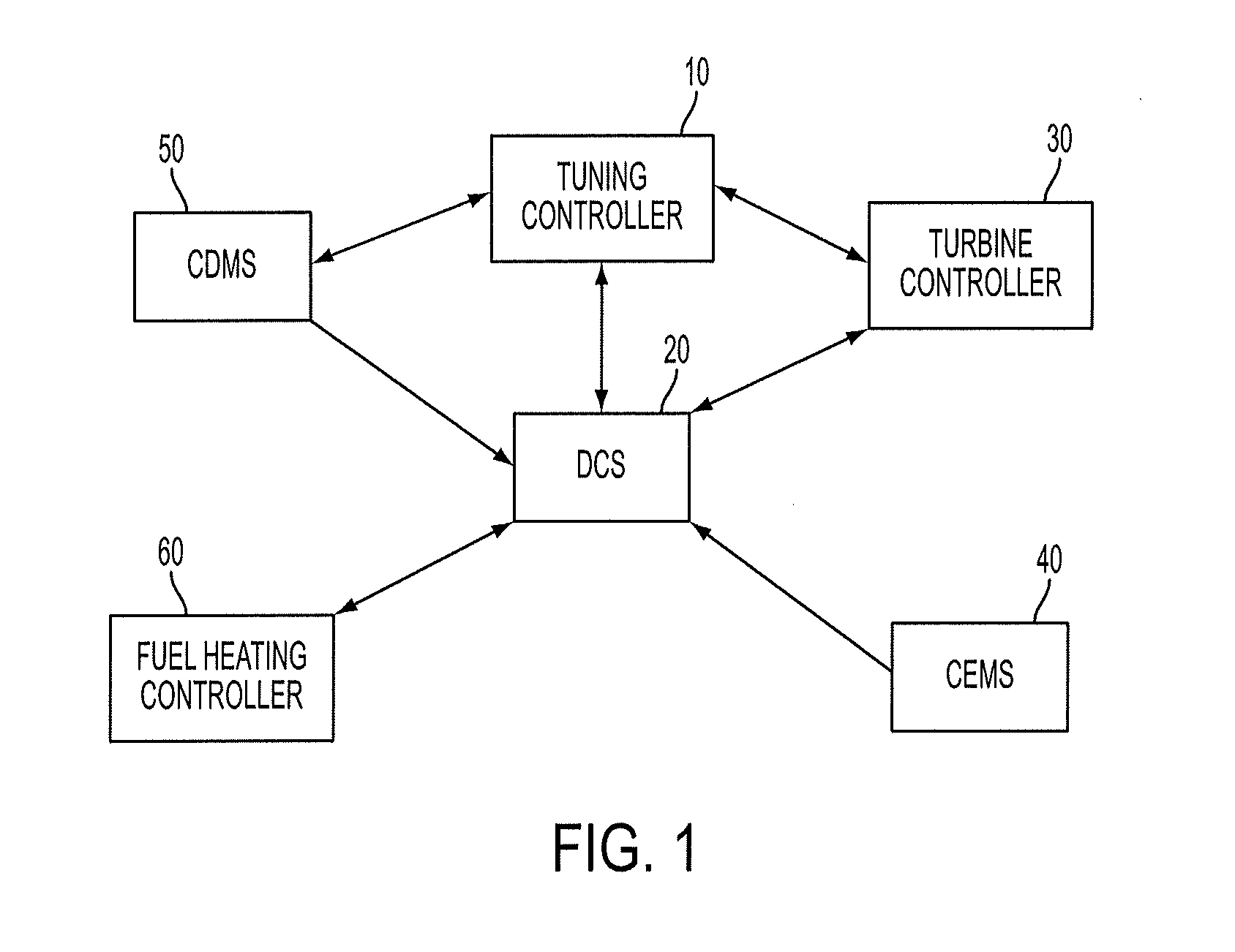
[0041]FIG. 1 shows a communication diagram for a gas turbine engine (not shown), within which a tuning controller 10 of the present disclosure operates. As shown, a communication link, such as a Distributed Control System (DCS) is identified by th...


PUM


Abstract

The present disclosure provides a tuning system for tuning the operation of a gas turbine. The system comprises operational turbine controls for controlling operational control elements of the turbine, including at least one of turbine fuel distribution or the fuel temperature. The system also has a tuning controller communicating with the turbine controls. The tuning controller is configured to tune the operation of the turbine in accordance with the following steps: receiving operational data about the turbine, providing a hierarchy of tuning issues, determining whether sensed operational data is within predetermined operational limits and producing one or more indicators. If the operational data is not within predetermined operational limits, the tuning controller will rank the one or more indicators to determine dominant tuning concern, and tune the operation of the turbine based on dominant tuning concern. Also provided herein are a method and computer readable medium for tuning.

Description

CROSS-REFERENCE TO RELATED APPLICATION [0001]The present application is a continuation-in-part of pending U.S. application Ser. No. 12 / 463,060 filed on May 8, 2009. The contents of pending U.S. application Ser. No. 12 / 463,060 are hereby incorporated by reference in their entirety.TECHNICAL FILED [0002]The present disclosure relates to an automated system to sense the operating condition of a turbine combustion system and to make adjustments to achieve desired operation of the turbine combustion system.BACKGROUND [0003]Lean premixed combustion systems have been deployed on land based gas turbine engines to reduce emissions, such as NOx and CO. These systems have been successful and, in some cases, produce emission levels that are at the lower limits of measurement capabilities, approximately 1 to 3 parts per million (ppm) of NOx and CO. Although these systems are a great benefit from a standpoint of emission production, the operational envelope of the systems is substantially reduced...

Claims


Application Information

Patent Timeline
Patent Type & Authority Applications(United States)
IPC IPC(8): F01D17/00F01D25/00
CPCF02C9/28F05D2270/31F23N1/002F23N5/003F23N5/242F05D2270/083F05D2260/80F23N2041/20F23R2900/00013F05D2270/303F05D2270/082F23R3/34F23N2241/20F05D2220/32F05D2270/20G05B13/021
Inventor CHANDLER, CHRISTOPHER
Owner GTE TURBINE EFFICIENCY SWEDEN AB
Why Eureka
Try Eureka